
Now that your fins have dried, it's time to sand them smooth.
They'll be pretty rough when you start. The CWF will have formed ridges and clumps, and you need to knock all that off before you get to the finer sanding.
 |
| A fin from my Crossfire ISX - again, I neglected to take pictures of the Big Bertha fins here. See how rough the fin looks? You need to sand off those brush marks. |
Now, when I started doing this, I assumed you sand until all the CWF is gone, and the balsa grain would be filled. CWF is good, but not that good. If you sand off all the CWF, you're going to see wood grain in your paint job. So, what you want to do is sand most of the wood filler off and leave just a thin layer or skin of it.
You'll likely expose a bit of wood. This is fine for now. Just go slowly and be careful. I find that the edges of the fins have exposed wood while the center is still coated in CWF. This is probably due to either a very slight warp in the fins, or not having the sandpaper tightly enough against the sanding block, or possibly pressing too hard toward the outside. Either way, it's kind of unavoidable sometimes. We're going to repeat this process, so don't sweat it.
Sand the edges carefully, finding that rounded edge without overdoing it and sanding any of the wood off. Sand the root edge if you have any CWF on it, and make sure it's flat. I stand my fins on the root edge to make sure they're square.
Blow away any dust from the sanding so you can see what you're doing. When you're done, most of the fins will be incredibly smooth - with some imperfections...

As I was doing my initial sanding, I accidentally gouged one side of the fin. I was sanding on a piece of newspaper that had some bits of stuff underneath, and pressing down made these indentations. Also, you might be able to see at the edge some exposed wood.
Gouges are what CWF was made for. I needed to recoat the fins anyway, so I made sure to use a putty knife to really push the CWF into the indentations. Do another coat of CWF, let dry, and sand again. Then do it again. About three coats should really do it, unless you get lucky with your second coat. You can thin the CWF out a little bit more on your third coat, so you use less and have less to sand off.
When you're satisfied, you're done. Wipe off any dust from the fins with a slightly damp paper towel, and dry them immediately. Set the fins aside for now.
Now, let's turn to the motor mount, or engine mount. In most rocket kits, this is a short tube which is narrower than the body of the rocket, and is held in place with a couple of rings of cardboard or round paper, called centering rings. Some rockets have no mount, as the body is the same size as the motor used, so the motor goes right into the body of the rocket. This is called a minimum-diameter rocket, as the rocket is no fatter than it needs to be to accommodate the motor. This is what you use for rockets that go high and fast, as the weight is kept to a minimum.
 |
| The Estes Hi Flier is a minimum-diameter rocket. The body tube is the motor mount! That stand is actually a standard motor - just the right size to fit the body. |
The motor mount usually also has a metal hook attached to it, called an engine hook. This keeps the motor in the rocket. Inside the motor mount, you also usually have something called an engine block or thrust ring. This is just a ring of paper which keeps the motor from shooting out through the top of the rocket, destroying everything in its path.
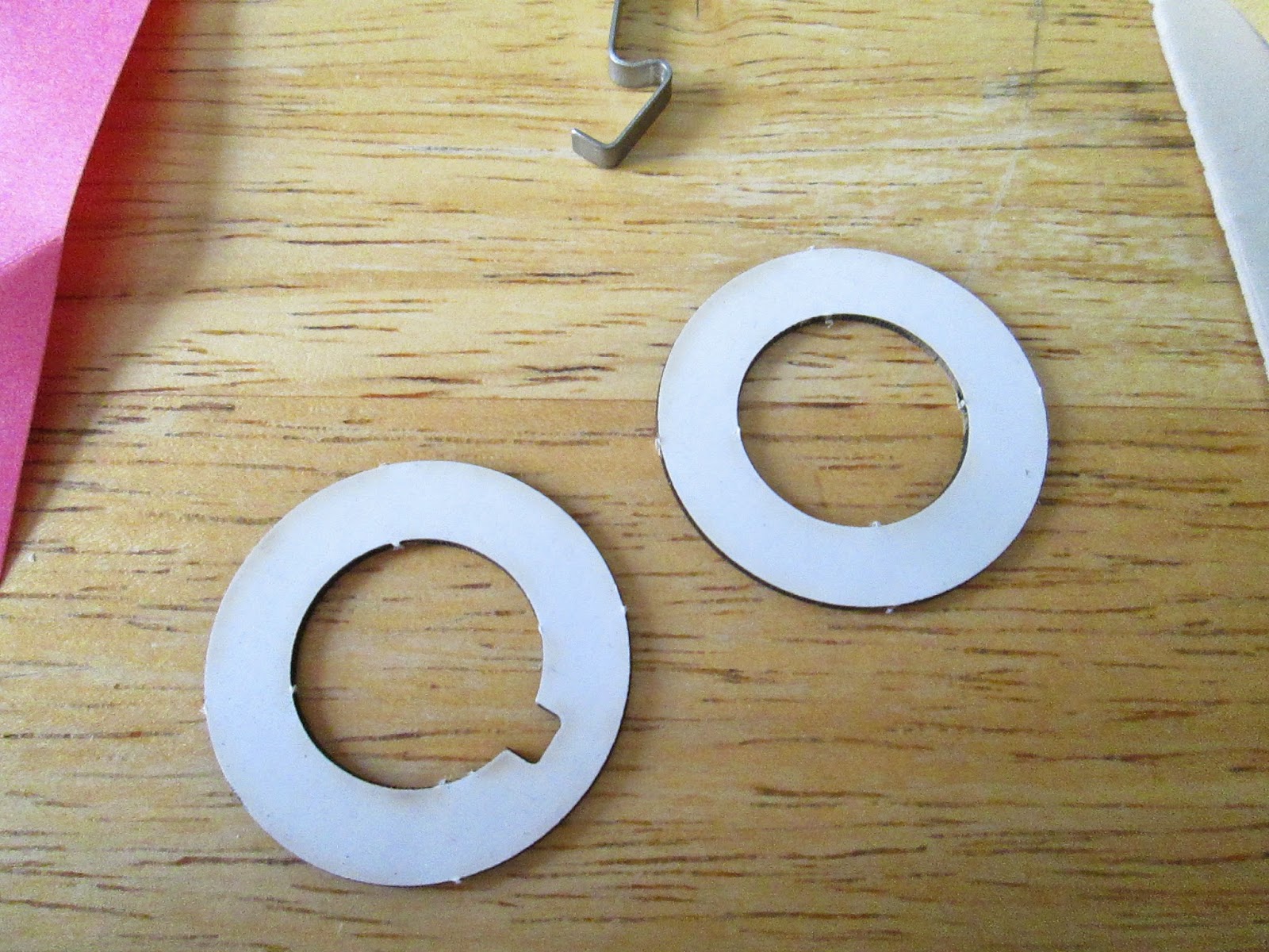
 |
| Motor mount parts - 1) Motor tube 2) Centering rings 3) Engine hook 4) Mylar hook sleeve 5) Engine block/thrust ring |

 |
| These marks, from top to bottom, are where the engine hook will be inserted, where the hook sleeve will go, and where the aft centering ring will be glued. I tend to mark the fore and aft ends of the motor tube so as not to make a dumb mistake. |
 |
| 1/8 inch slit for the motor hook |
 |
| Mylar hook sleeve glued in place. Don't glue down the aft end of the hook - you need it to bend to insert a motor! |
These have to be well-glued. Make sure they'll fit before you glue them, sanding them a bit if they're too tight. Then apply a liberal amount of wood glue around the tube where they'll go and slide them into place. There should be enough glue to make a fillet - extra glue at the joint - to reinforce the bond.
 |
| Engine mount finished, waiting for glue to dry. You can see the engine hook, the centering rings, the Mylar hook sleeve, and glue fillets at the joints. The engine block/thrust ring is inside, toward the base in this photo. |
Apply a good amount of wood glue about 1 1/2 - 2 inches into the base of the rocket. You need a ring of it, and you want to be kind of liberal with it. First, you want to push the glue into place, and you want it to form a reinforcing fillet of glue when it comes to rest. Second, if you use too little glue, the glue can seize up, and the motor mount can get stuck only halfway into the rocket!
You can apply the glue with a small dowel rod or craft (popsicle) stick, but I have gotten to where I just use my fingers. I can feel that I've gotten enough glue in, and I'm less likely to get glue where I don't want it if I go by feel rather than using a stick.
Push the motor mount halfway in, and apply some more glue about a quarter inch inside the base of the rocket. Push the motor mount into place, with the motor tube either flush with the base of the body tube, or with about a quarter inch of overhang (depending on your kit's instructions).
 |
| Installing a motor mount - in this case, in my Cosmic Explorer. Again, I didn't photograph this part of the Big Bertha build... |
Stand the rocket body tube on the fore or top end and allow all the glue to dry for at least a couple hours. I leave it overnight.
In the next post, we'll actually have (gasp!) pictures of the Big Bertha build. And we'll learn some Rocket Pro Tips on getting a good surface for painting. We're getting closer to finishing this thing!
[Click here for Part 4]
No comments:
Post a Comment