

As a member of the National Association of Rocketry, I regularly get an email newsletter - The Electronic Rocketeer - from Ted Cochran, president of the NAR.
In the most recent edition, sent out on January 31, Ted addressed the issue of repairs and safety.
"While it can be a badge of honor to put up 100 flights on a single model over the years, we do need to pay attention to how we make repairs so as to ensure the models remain safe.Good points.
"Fin alignment, CP/GG ratios, structural integrity, and aerodynamics all have to be maintained or restored during repairs. We need to be sure the airframe remains strong and rigid--use couplers that are at least twice as long as the diameter of the body tubes for splices.
"If we need to add weight to the aft end to repair fins, we may need to add weight to the nose to maintain stability. As we add weight, we may need to select a shorter delay to accommodate the resulting decreased performance.
"We also need to inspect for less obvious damage, such as centering rings/motor mounts broken loose from the body tube, cracked fins, damaged recovery harnesses, and body tube kinks--especially just above the fins.
"If we're as careful repairing the rockets as we are building them in the first place, they may provide dozens or even hundreds more great flights!"
* * *
At my last launch of the season, I had a few bad flights, resulting in damage to a couple of my rockets. The most heartbreaking one was the damage to my Magnum Sport Loader, by Quest Aerospace.

A nose dive into the mud caused a tear extending about an inch and a half into the forward end of the airframe. The advice I got on repairing this rocket was simply to cut the damaged part off, rather than trying to restore it to its full length. It would be shorter, but it would still look good and fly well.
The Sport Loader is a payload rocket, with a large enough payload section to hold two raw eggs.

Up to now, that's all I'd flown in it. But there are a number of things you can fly in a payload section, one of them being an altimeter.
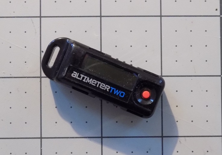 |
| My Jolly Logic Altimeter Two, which has not yet flown |
I built the Sport Loader early on in my rocketry... "career" sounds funny, but I don't know what other word to put here. Anyway, I didn't take using an altimeter into account when I built the rocket. The payload section is pretty airtight - so much so that when you open it, there's an audible pop! like pulling a cork from a bottle.
In fact, I don't have any rockets finished which are set up to fly with an altimeter. A sealed payload section like that won't depressurize as the rocket flies upward, so the altimeter won't measure much, if any, change in altitude.
The solution is to provide ventilation to the payload section, so that it can equalize with its outside environment. This is accomplished by drilling holes into the payload section. Since I really liked the way the Sport Loader looked, much as I wanted to see how high it flew, I didn't want to mar the paint job by drilling into it. But since the rocket would not be "perfect" any more, I took this as an opportunity!
Holes for pressure equalization for a payload bay are referred to as static ports. In order to maintain symmetry with the layout of the rocket (three forward fins, three aft fins), I decided on three static port holes.
In order to place the static ports evenly around the payload section, I created a fin marking guide in OpenRocket for a tube of the correct diameter - about 1.91 inches.

I wrapped the fin marking guide around the body, about 1/4 inch forward of the lower decal stripes.

I definitely didn't want to risk drilling into the decals, but it's important to have the static ports more toward the aft end of the payload bay. It's generally recommended that you put static ports at least as far back from the nose cone/body tube joint as the diameter of the body tube. This is to avoid some of the turbulence you get over that joint, which can affect the accuracy of the altimeter readings.
After marking the locations for the static ports with a pencil, it was time to drill. You can do this with a hand drill, but since I recently got a deal on a drill press, I decided to try using it for the first time - worked like a dream!
I drilled 3 3/32 inch holes evenly spaced around the payload compartment.

The holes are a little rough around the edges, so I wicked in some thin CA - cyanoacrylate or super glue - to harden the paper fibers. I'll have to gently sand off the raised ridges, while trying not to remove too much paint.
Next, it was time to cut off the damaged portion of the body tube.
To cut a tube, you can wrap a piece of paper around the frame so that the edges line up, and carefully cut along the edge with a hobby knife. Since I don't think I'd do that so well without making a mess of it, I used a tool I made - a Kuhn tube cutting jig.

This is for cleanly cutting body tubes to a specific length. It was designed by pioneering model rocketeer Howard Kuhn. You can get a kit to build one of these by North Coast Rocketry, from Apogee Components or a few other vendors.
I wanted something which could easily cut larger tubes, was impatient about shipping, and wanted to try my hand at making my own, so I built this. It works great!
To use a Kuhn tube cutter, you set the length of tube you want with the wooden block and clamp it into place. Then you place a razor blade or utility knife blade into the little notch. Set the end of the tube you want to cut against the wooden block, hold the blade steady with your right hand, and gently press it against the tube. With your left hand, slowly turn the tube around and around. You don't want to try cutting all the way through in one go, and you do have to go slowly so the blade doesn't wobble, or you won't get a straight cut - the jig is nice, but it does require some finesse.
Eventually, you should have a clean cut all the way through the tube.
Due to the ripped body tube, my turning was a little uneven, so I got a kind of wobbly cut.

Not to worry - I tucked the shock cord down inside the body tube, and ran a ring of thin CA around the inside edge of the tube. I wiped off the excess CA with a paper towel and allowed it to dry, then sanded the edge of the tube straight with a sanding block.

Ta-daa! Good as (almost) new! You almost don't even notice that the rocket is a bit short, and now I can fly it with an altimeter.
But, wait. Remember what Ted Cochran said about safety? I've altered the length of the rocket, and that will change where both the Center of Pressure (CP) and Center of Gravity (CG) are. That could affect the stability of the rocket.
Before flying the rocket, I need to check its margin of stability, also known as its static margin. We'll do that in Part 2.
Click here for Part 2.
Like my Facebook page for blog updates and extra stuff.
No comments:
Post a Comment