This is kind of an addendum to the previous two posts on repairing the Quest Magnum Sport Loader and then verifying its flightworthiness. The actual model is finished, stable, and ready to fly. Now, I want to fix the simulation in OpenRocket to reflect the actual model.
Why do I want to do this? A couple of reasons. The first is curiosity: I want to see how accurate OpenRocket is in finding the correct Center of Gravity (CG) when I load different motors. Sometimes I look at the CG on a RockSim or OpenRocket file, and wonder can that really be right?
But more importantly, I want to be able to run flight simulations before I actually go out to launch the rocket. Depending on weather conditions - wind, mainly - I might decide to put different motors in the rocket. On a particularly breezy day, a high flight increases the likelihood that I will lose one of the models I'm proudest of. And if I fly an altimeter in the payload compartment, that could be an expensive loss. Running a flight simulation will give me a rough idea of how high the rocket will fly with different motors. I can then make a more informed decision whether to put A, B or C motors into the rocket, depending on how high I am willing to let the rocket fly on launch day.
I can then also compare the simulation to the data from actual flights, recorded on the altimeter. I can see how close to the predicted altitude the rocket actually flew. Then I can look back at the simulation and figure out how I might make the predicted altitude more accurate. That's part of what makes rocketry interesting. There's more to it than just watching something go up and come down.
I think I should mention that as good as rocket simulators are, they're almost never 100% accurate when it comes to altitude prediction. There are just too many variables to account for in the physical flying environment. But they're pretty good, and much better than guessing. And, as I said before, I'm not a master at OpenRocket, but I know enough for a beginner to be reasonably accurate.
Let's get started.
First thing, I start OpenRocket, and open the original RockSim file, downloaded from the Apogee Components website. This is what I see.
This original design file has not been altered to reflect the shorter, repaired rocket. Before I do any of that, I'm going to "Save as" an OpenRocket file. OpenRocket and RockSim are mostly compatible, but not 100%. Sometimes, if you make a change to a RockSim file in OpenRocket, then save all your changes and close the file, you will find when you go back to the file, some of the changes you made have not been saved. Saving the file as an OpenRocket (.ork) file will fix this problem.
Up in the design box, we see a number of things we'll want to change.
Every weight symbol means that the mass, or weight, of something has been overridden. Every blue and white circle (the CG symbol) means that the CG of something has been changed. These are on several components, but in fact they don't matter as much as the overrides on the part called Stage. That refers to the entire rocket (or to the upper stage, if this were a two-stage rocket). Overriding the mass and CG on Stage overrides everything else below it.
We're going to get rid of all the overridden data for this simulation and input our own.
The rocket's mass has been overridden in the simulation. With no motors, it is said to weigh 99.2 grams.
When you remove part of a rocket in real life (in this case, we removed nearly 2 inches of the airframe when we repaired the rocket), the mass will change a bit. But in the last post, you saw that simply shortening the airframe in the design file wasn't enough - because the CG had been overridden to 35.6 cm, no matter how much I shorten the tube, the value won't change.
Obviously the Center of Gravity can't be behind the rocket!
That's the same for the mass. In fact, since the override on Stage outranks any other override on any component, I could make each of the fins weigh 20 pounds, and the simulator will still say that the rocket weighs 99.2 grams.
First thing I'll do is remove the mass override for Stage. Double-clicking on Stage on the design components box brings up a dialog box.
Simply remove the check mark in the Override mass box, and the mass of the rocket will equal the combined mass of all the parts.
Suddenly, the rocket is said to have a mass of 281 grams! That's a huge difference.
The CG, however, remains where it is - 35.6cm from the tip of the nose cone. We'll remove that override as well.
Incidentally, you can use either grams or pounds and ounces. I am sticking with grams for now, because I have a digital scale which uses metric and is accurate to 0.1 gram, and I'll use that to complete the simulation here.
Let's get rid of the CG override.
Suddenly, the CG jumps way forward, to 16.9cm from the tip of the nose cone, in the lower third of the payload section.
And here we see why the rocket weighs so much. There are "mass components" in the payload section, representing the payload this rocket is designed to carry - in this case, raw eggs.
Oddly, though the rocket only has a capacity for two eggs, there are three of them represented here. They are called "Egg1," "Egg2," and "Unspecified," but they all seem to represent eggs, because they all weigh about the same - 63 grams.
Two of them are hard to see, because they have been assigned a length of 0 by the person who built this simulation. One of them is located exactly where the nose cone meets the black coupler attaching it to the payload section. You can see it more clearly if I highlight it.
Raw eggs are heavy - about 2 ounces a piece. And three of them won't even fit in this rocket. Besides, we want to get an idea of what the rocket will do with no egg payload at all. If we want to fly one or two eggs, we can add these back to our simulation.
I select each egg in the design elements box and delete them. The CG has now shifted aftward, and the total mass of the rocket is now said to be 98.7 grams.
Now we're getting closer. I'm going to make a few more alterations to the simulation before turning to the physical rocket to take my measurements.
First, I've decided to fly the rocket with only one parachute. The rocket is designed to separate at apogee and come down on two chutes - the payload comes off and descends on its own parachute. I have decided I don't like this for a couple of reasons - I want to keep the parts of the rocket together, and I'm not confident the chute for the rocket booster will always come out of the airframe without the weight of the nose cone pulling on it. So I'm going to delete one of the parachutes, as well as the mass overrides and CG overrides of any components which have them. I'm also adding a shock cord, because the rocket obviously has one, despite the fact that it's not present in the design file. Finally, I'll shorten the airframe to match the repaired rocket I have.
I'll go back to the simulation and override a few things once I've weighed and measured the physical rocket itself. For now, though, I have a simulation file which is of accurate length to match the model I have on hand, with a CG said to be 24.8cm from the tip of the nose, and a mass of 101 grams with no motors installed.
What I need to find out to have a reasonably accurate simulation - and one which will tell me if the rocket is stable - are two things: The actual weight or mass of the completed rocket (with no motors installed) and the actual Center of Gravity of the completed rocket (again, with no motors installed). I can then input that information into the simulation. Finally, I'll find the CG of the rocket with motors installed, and see how accurate the CG in the simulation is with virtual motors installed in the simulation.
I was worried I talked CG and Gheem's ears off, but the episode turned out pretty good.
We've been on a roll with this season, and we have more exciting stuff coming up. We're working on a longer story about Joe Barnard's project, a finless, actively stabilized rocket using thrust vectoring, which he is attempting to land using motor thrust for recovery - just like SpaceX and Blue Origin.
The aft of Scout, Joe Barnard's rocket. Seen are two motors - a large one for ascent, and a small one for recovery.
The rocket is stabilized by thrust vectoring. The motors are on a gimbal - just like a real space launch vehicle.
This week, we are recording two exciting episodes.
We'll be talking with John Beans of Jolly Logic, maker of several model rocket altimeters, and an exciting new product - the Chute Release, which enables a model rocket to do something similar to dual deployment, but without black powder charges.
And another episode I'm thrilled we'll be recording this week will be with Mike Westerfield, author of the book Make: Rockets: Down-to-Earth Rocket Science. Mike has a new book coming out in the coming months, called Make: High Power Rockets. Longtime blog readers may have picked up that I'm kind of a Mike Westerfield fanboy, as his first book really helped me with my progress in rocketry. I can't wait for the publication of the new book!
Oh, and have I mentioned that we'll soon be talking to a real astronaut? Well, we are. Season 2 is turning out to be really great!
Like my Facebook page for blog updates and extra stuff.
In Part 1, I cut the damaged portion of the Quest Magnum Sport Loader off, shortening the airframe by about 1 3/4 inch. The rocket now looks good, despite being shorter, and because I drilled some static ports - vent holes for a barometric altimeter - into the fat payload section, I can now launch the rocket with an altimeter on board, which will tell me how high it flies.
Now, I have to make sure the rocket is safe to fly. Just looking at the shortened rocket, it looks fine. If I didn't know it had been altered from its original design and build, I would assume it was perfectly safe to fly.
The repaired, shortened, Sport Loader
But I don't want to guess or assume - I want to make sure. That requires a few easy steps.
If you've read my posts on stability, or if you've read the Handbook of Model Rocketry by G. Harry Stine and Bill Stine, then you know that rocket stability depends on the relationship of the Center of Gravity (CG) and the Center of Pressure (CP). In short, the Center of Gravity must be forward - closer to the nose of the rocket - of the Center of Pressure. How do we know where the CG and CP are? How far forward does the CG have to be from the CP? And if the CG is too close to the CP - or, even worse, behind the CP, how do we fix that?
The picture above is a simulation of the rocket, as seen in OpenRocket, free, downloadable rocket simulation/design software. In the picture, the blue and white circle represents the CG, and the red circle represents the CP. As you can see, the CG is ahead of the CP, which means that the rocket is stable.
We'll come back to rocket simulation software in a bit. For now, let's concentrate on the actual, physical rocket in question: The shortened Sport Loader.
Finding the Center of Gravity is simple, so let's start with that.
Another term sometimes used to describe the Center of Gravity is its balance point. This is because when you've found the CG, the rocket will balance perfectly. (Center of Gravity is also sometimes referred to as Center of Mass, because that's really what it is.)
To find the CG of a rocket, simply balance the rocket. You can balance it on your finger, or the back of a chair, or anything you have handy. My preferred method is to use a loop of thick string.
I used to use the back of a chair, but it was hard to balance the rocket perfectly. Sometimes it would roll, and I had to make the tiniest little adjustments so it wouldn't fall off. Sometimes it tries to roll off my finger as well. The string holds the rocket in place, so you can really see where it balances.
Above, you can see that I've found the CG of the rocket - but this is the CG of the rocket with no motors installed. I'm going to mark that spot, and plug it into my simulation file later.
The forward edge of the blue tape marks the CG of the Sport Loader with no motors installed.
I'll explain why the rocket's nose is against the wall in a bit.
But for determining stability, we need to find the CG of the rocket from the moment it lifts off. That means we need to find out where the CG is when the motors are installed. Since this is a two-motor cluster rocket, the two motors should shift the CG significantly backwards.
To do this, you load the motor(s) into the rocket, as well as the parachute and recovery wadding - anything that goes into the flying rocket goes in when checking stability.
Once again, I balanced the rocket to find the new CG.
You can see the CG has shifted aftward dramatically. I'll mark that spot with blue tape as well, and compare them.
In this photo, the nose is beyond the left hand side of the picture. You can see the
difference in CG when the rocket is loaded with motors, compared with when it is empty.
* * *
Now that we've found the CG for the rocket, with everything loaded in it for flight, I'm going to interrupt this post for a moment, and I figure this is the right place to do it. If I don't, then after reading this whole post, someone is sure to write in the comments, "Just do a swing test."
What is a swing test? It's a simple (and fun) test to check whether a model rocket will be stable in flight.
To do a swing test - sometimes known as a string test, you'll need the loaded rocket and a long piece of string. The longer the string, the better, so long as you can actually get the rocket swinging. At least six feet long is recommended.
Simply find the CG, as above, with the loop of string - the string I'm using here is a strong piece of Kevlar, but any sturdy string, such as kite string, will do. What you then do is tape the string in place to the underside of the rocket, so that the loop will not slip, and the rocket will stay in place.
Go outside, hold the string in one hand above your head, and hold the rocket out at arm's length, with the nose pointed forward. Make sure nobody is standing too close to you. Begin turning your body in the direction of the nose and give the rocket a little push with your hand to get it started. Swing the rocket around and around, letting the string out to its full length. If the rocket flies nose first, you know it's going to be stable in flight. It might take a few tries to get it to fly right, but if it does, you can skip the whole CG/CP measurement if you want to.
It's also a fun test to do, because you get to see kind of what the rocket would look like in flight, but from a close vantage point, which you never get to do when the rocket is actually launched.
Here's a good video with a swing test in it.
So, why not "just" do a swing test? There are a few reasons. For one, maybe you don't have the room. As I write this, it's winter, so it's cold outside, and I don't have a lot of space outside that isn't populated by cars, houses or shrubbery.
Another reason is that some rockets do not pass the swing test, yet are perfectly stable. I'll elaborate on this point when I write Part 3 of my stability series, but I'll just briefly say that long rockets or rockets with large fins sometimes have a hard time flying straight on a swing test. And larger rockets are harder to get swinging at a fast enough speed for the swing test to work, especially without hitting something.
Yet another reason for going beyond swing testing your rocket is that perhaps you're interested in understanding the rocket's stability in a more theoretical way. Calculating the CG/CP relationship is interesting - it's the theoretical part of rocketry. Then, swing testing or launching the rocket once you've determined stability is the experimental part. That's fun science! I find the swing test useful as a way of double-checking my work. A failed swing test prompts me to take careful measurements, to see if I really do need to modify the rocket.
If your rocket passes the swing test, it will be stable. If it doesn't, then you need to go on to the next step.
* * *
Now we need to find the Center of Pressure - CP.
The easiest and most reliable way to do this today is with rocket simulation/design software. There are several kinds, but the most common are RockSim and OpenRocket.
RockSim is sold by Apogee Components. It's a fine software, quite sophisticated, and a lot of rocketeers swear by it. If you get serious about rocketry - especially scratch building and high power rocketry - it's a good investment. But it does cost over $123. You can download a free three-month trial of RockSim if you're curious about it.
OpenRocket is free to download and use. It uses Java, so you'll need to have that installed on your computer. It lacks some of the bells and whistles of RockSim, but it's a good place to start for beginners, and some rocketeers simply stick with it, because they don't necessarily need the few extras RockSim provides. One of my fellow club members, an experienced rocketeer who flies lots of high power rockets, uses both software to run simulations before he launches. As he puts it, "Sometimes it's good to have a second opinion."
Center of Pressure is determined by the shapes and sizes of all the external components. It has to do with the relative surface areas of all the parts. As such, it doesn't matter whether your nose cone is heavy or light, or what materials your fins are made of - just what size things are and where they are placed on the rocket. Most specifically, what puts the CP toward the aft of the rocket, where it should be, is the fins.
If you're very meticulous about measuring all parts of your rocket, getting the shapes and angles of the fins correct, figuring out the exact length-to-diameter ratio of your nose cone, etc., you can create a pretty good simulation of your rocket on your own. But if you are using a kit, such as from Estes or Quest, you can very likely find a good sim file somewhere online of your very rocket.
Since the Sport Loader is sold by Apogee Components, I was in luck. Apogee has kindly put free RockSim files of most of the rockets they sell on their website. I use OpenRocket, but I can still open and modify RockSim files with it. The two software are mostly compatible.
I open the Sport Loader RockSim file, and here's what I see.
You can see that the CG is well forward of the CP. In the top right corner of this image, you see the following information:
Stability:2.48 cal
CG:35.6 cm
CP:47.7 cm
This is the stability information for the original rocket without motors. CG and CP locations are measured from the tip of the nose cone. So, in this instance, the CG is 35.6 centimeters from the tip of the nose cone, and the CP is 47.7 centimeters from the tip of the nose.
Incidentally, when taking stability measurements, I always use the metric system. It's much easier, since everything is divided by 10 (how do you measure 15.655 inches with a ruler?), and millimeters are small enough units that if you get a measurement to within less than a millimeter of accuracy, you're probably going to be just fine.
"Cal" is short for caliber, and it refers to the distance between the CG and CP. Caliber is based on the diameter of the rocket itself - more precisely, on the diameter of the widest part of the rocket, which, in this case, is the payload section. This distance between the CG and CP is called its static margin of stability.
In order for a rocket to remain stable in flight, the static margin must be at least 1 caliber. The reason for this is that the Center of Pressure can move forward, depending on the flight conditions. If the CG moves too close to the CP, the rocket will be neutrally stable, and if it goes forward of the CG, the rocket will be unstable, and will flail around in flight.
With the Sport Loader, we have a rocket whose widest diameter is 4.9 centimeters, or 49 millimeters. That means that in order to maintain a minimum static margin of 1 caliber, the CG must be at least 49 millimeters forward of the CP. Anything less than 1 caliber stability is referred to as marginally stable, and is not safe enough for flight. In the image above, the CP is 12.1 cm forward of the CP, giving us a static margin of 2.48 caliber.
Of course, rockets do not fly without motors, so let's see what the static margin is with the motors installed.
The CG has shifted aftward to 42.1 cm from the tip of the nose, and we still have a safe static margin of 1.14.
Well, that's great for our original rocket, but what about our newly-shortened, repaired rocket? We'll need to re-measure that.
I want to make my simulation as accurate to the real rocket as possible, so I need to measure the new, shorter length of the tube.
Looks like I've cut the body tube down to about 33.2 centimeters in length. Why don't I just change the design in OpenRocket and see if the rocket is stable? That should work, right?
Let's take a look.
Whoa, what?? I take off an inch and three quarters, and suddenly the rocket has a stability margin of 0.627? The rocket looks like it should be stable, so why is it now marginal?
Here's a clue - the Sport Loader with a very short, stubby tube:
I've shortened the body tube to about 7 centimeters or so, and now the CG is behind the rocket!
Of course, this doesn't make sense. But I'm showing it to you, because it took me some thinking to figure out what the problem was. OpenRocket doesn't come with instructions, and for about a year, there were two important functions I was completely unaware of: the ability to override both the mass of the rocket, and the rocket's Center of Gravity. That's what's going on here: the CG in the RockSim file has been overridden.
The design elements box in OpenRocket. The CG symbol means that the
Center of Gravity has been overridden. The little weight symbol
means that the mass has been overridden.
This is because when you build a rocket in simulation software, it calculates roughly where the CG will be by finding the CG of the individual components. But it doesn't take into account certain key components - namely, the kind and amount of glue or epoxy you use to build the rocket, and the weight and thickness of paint. Often, a person will build a simulation of a rocket, then compare the calculated CG with the CG of the real, built rocket, then override the CG in the simulation. This will help you to get better simulations.
The fact is, no matter how accurate a simulation may be, you still need to verify the measurements on the actual rocket, when making repairs or modifications. So, while simulations can be useful, for now, let's get back to the real rocket. What we need to do is find, measure, and mark the CP on the rocket we have.
The simulation tells us that our new Center of Pressure is located 43.8 cm from the tip of the nose cone. You could take a cloth tape measure, put it on the tip of the nose cone, and measure from there. But to be truly accurate, you need to measure straight back from where the tip of the nose cone. That's why I placed the nose cone against the wall in the pictures above. I'm going to measure from the wall, which will be on the same plane as the tip of the nose, back to the CG and CP.
It's kind of like when you go to the doctor and they measure your height - they use a straightedge to find the top of your head.
So, from the wall, where the tip of the nose cone is placed, I used a rigid, metal tape measure to mark a spot on the rocket 43.8 cm from the tip of the nose cone.
I've already marked and measured the CG for the rocket, both with no motors, and with motors installed.
With the motors (and parachute and recovery wadding) installed, the real CG of the rocket is about 36.1 cm from the nose.
That's a difference of about 7.7 cm.
The rocket is about 4.9 cm in diameter at its widest point - the payload section. The static margin is larger than 1 caliber - I have now verified that the rocket will be stable, and is safe to fly.
So, why did I bother checking the CG on the simulation, instead of just using it to find the CP, which is all I needed to do here? And why did I mark the CP of the rocket with no motors installed, if I only needed to find the CP with the motors in to check stability?
The answer is that I wanted to be able to run accurate simulations of my rocket in the future. We'll talk briefly about that in the next post.
For now, though, if you alter a rocket in any way, through repair, or through upgrading a kit to take a larger motor - which I have done, and it's been a lot of fun - take these steps, and you can be sure your rocket will be stable.
As a member of the National Association of Rocketry, I regularly get an email newsletter - The Electronic Rocketeer - from Ted Cochran, president of the NAR.
In the most recent edition, sent out on January 31, Ted addressed the issue of repairs and safety.
"While it can be a badge of honor to put up 100 flights on a single model over the years, we do need to pay attention to how we make repairs so as to ensure the models remain safe.
"Fin alignment, CP/GG ratios, structural integrity, and aerodynamics all have to be maintained or restored during repairs. We need to be sure the airframe remains strong and rigid--use couplers that are at least twice as long as the diameter of the body tubes for splices.
"If we need to add weight to the aft end to repair fins, we may need to add weight to the nose to maintain stability. As we add weight, we may need to select a shorter delay to accommodate the resulting decreased performance.
"We also need to inspect for less obvious damage, such as centering rings/motor mounts broken loose from the body tube, cracked fins, damaged recovery harnesses, and body tube kinks--especially just above the fins.
"If we're as careful repairing the rockets as we are building them in the first place, they may provide dozens or even hundreds more great flights!"
Good points.
* * *
At my last launch of the season, I had a few bad flights, resulting in damage to a couple of my rockets. The most heartbreaking one was the damage to my Magnum Sport Loader, by Quest Aerospace.
A nose dive into the mud caused a tear extending about an inch and a half into the forward end of the airframe. The advice I got on repairing this rocket was simply to cut the damaged part off, rather than trying to restore it to its full length. It would be shorter, but it would still look good and fly well.
The Sport Loader is a payload rocket, with a large enough payload section to hold two raw eggs.
Up to now, that's all I'd flown in it. But there are a number of things you can fly in a payload section, one of them being an altimeter.
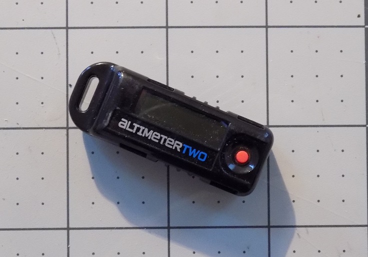
My Jolly Logic Altimeter Two, which has not yet flown
An altimeter uses the change of barometric pressure outside the ascending rocket to measure altitude - as the rocket climbs higher, the air pressure drops.
I built the Sport Loader early on in my rocketry... "career" sounds funny, but I don't know what other word to put here. Anyway, I didn't take using an altimeter into account when I built the rocket. The payload section is pretty airtight - so much so that when you open it, there's an audible pop! like pulling a cork from a bottle.
In fact, I don't have any rockets finished which are set up to fly with an altimeter. A sealed payload section like that won't depressurize as the rocket flies upward, so the altimeter won't measure much, if any, change in altitude.
The solution is to provide ventilation to the payload section, so that it can equalize with its outside environment. This is accomplished by drilling holes into the payload section. Since I really liked the way the Sport Loader looked, much as I wanted to see how high it flew, I didn't want to mar the paint job by drilling into it. But since the rocket would not be "perfect" any more, I took this as an opportunity!
Holes for pressure equalization for a payload bay are referred to as static ports. In order to maintain symmetry with the layout of the rocket (three forward fins, three aft fins), I decided on three static port holes.
In order to place the static ports evenly around the payload section, I created a fin marking guide in OpenRocket for a tube of the correct diameter - about 1.91 inches.
I wrapped the fin marking guide around the body, about 1/4 inch forward of the lower decal stripes.
I definitely didn't want to risk drilling into the decals, but it's important to have the static ports more toward the aft end of the payload bay. It's generally recommended that you put static ports at least as far back from the nose cone/body tube joint as the diameter of the body tube. This is to avoid some of the turbulence you get over that joint, which can affect the accuracy of the altimeter readings.
After marking the locations for the static ports with a pencil, it was time to drill. You can do this with a hand drill, but since I recently got a deal on a drill press, I decided to try using it for the first time - worked like a dream!
I drilled 3 3/32 inch holes evenly spaced around the payload compartment.
The holes are a little rough around the edges, so I wicked in some thin CA - cyanoacrylate or super glue - to harden the paper fibers. I'll have to gently sand off the raised ridges, while trying not to remove too much paint.
Next, it was time to cut off the damaged portion of the body tube.
To cut a tube, you can wrap a piece of paper around the frame so that the edges line up, and carefully cut along the edge with a hobby knife. Since I don't think I'd do that so well without making a mess of it, I used a tool I made - a Kuhn tube cutting jig.
This is for cleanly cutting body tubes to a specific length. It was designed by pioneering model rocketeer Howard Kuhn. You can get a kit to build one of these by North Coast Rocketry, from Apogee Components or a few other vendors.
I wanted something which could easily cut larger tubes, was impatient about shipping, and wanted to try my hand at making my own, so I built this. It works great!
To use a Kuhn tube cutter, you set the length of tube you want with the wooden block and clamp it into place. Then you place a razor blade or utility knife blade into the little notch. Set the end of the tube you want to cut against the wooden block, hold the blade steady with your right hand, and gently press it against the tube. With your left hand, slowly turn the tube around and around. You don't want to try cutting all the way through in one go, and you do have to go slowly so the blade doesn't wobble, or you won't get a straight cut - the jig is nice, but it does require some finesse.
Eventually, you should have a clean cut all the way through the tube.
Due to the ripped body tube, my turning was a little uneven, so I got a kind of wobbly cut.
Not to worry - I tucked the shock cord down inside the body tube, and ran a ring of thin CA around the inside edge of the tube. I wiped off the excess CA with a paper towel and allowed it to dry, then sanded the edge of the tube straight with a sanding block.
Ta-daa! Good as (almost) new! You almost don't even notice that the rocket is a bit short, and now I can fly it with an altimeter.
But, wait. Remember what Ted Cochran said about safety? I've altered the length of the rocket, and that will change where both the Center of Pressure (CP) and Center of Gravity (CG) are. That could affect the stability of the rocket.
Before flying the rocket, I need to check its margin of stability, also known as its static margin. We'll do that in Part 2.