Wednesday, December 29, 2021

Estes V2 Chain Drives - Making Your Own Scale Details


Some rocketeers have such good modeling skills, it's intimidating. Scale modelers working on tiny details can make a relative beginner feel like I have no idea how to do that. I'll never be that good. But that doesn't mean you can't try - things might turn out better than you expect, and the only way to get good at it is to do it.

I decided to try making chain drive covers, or servo pods, for the Estes V2. This isn't part of the kit, and making little parts is a real challenge for me. Tiny stuff frustrates me.

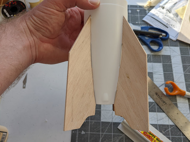
I decided to see if I could make these little details well enough to bother putting them on the rocket. These were done by eye, without much reference material, apart from some photos on the Internet and Peter Alway's Rockets of the World. I used leftover fin material to cut rough shapes I'd sand into the final form.

The kit fins are 3/32 inch thick, and these pods are surely not to proper scale. The fin stock is probably too thick, for one thing. They're also probably not shaped just right. But as I said in a previous post, I'm not going to be a stickler for scale accuracy. If they look pretty good and add to the model, that's good enough for me.

The pods are taller on one end than another. Stack sanding them all to the same shape was tricky. Once they all went flying and I found most of them, but had to cut an extra.

After cutting the rough shape out and sanding them all, I began by rounding the ends. Then I carefully rounded them over the tops.


Using a sanding block turned out to be really difficult, so I switched to a scrap of 400 grit sandpaper on my finger to do the rounding.


In the close-up photo you can see the imperfections, but really these turned out pretty good.


Without the extreme close-up, you don't really notice the inconsistency of shape. I decided to try gluing them on

They turned out great! True, they're not perfectly to scale, but I really feel they add something to my V2.

I ended up using Titebond Molding and Trim Glue to attach the pods to the fins. I usually use this white wood glue for fillets, and Titebond II for the rest of the build. But the Molding and Trim Glue worked out better in this case. Its "fast initial tack" helped in that I could place the chain drive pods in place with tweezers, and after a minute or so, press the piece down tight to the wood without it accidentally slipping out of place. Seems like a great choice for a piece you don't want to move around too much after placing it. I might start reaching for this stuff more regularly.

That said, the answer to the perennial model rocket newbie question "what's the best glue" is "pretty much any white or yellow glue." Even School Glue isn't as bad a choice as some people think (although I wouldn't use it). Use what you want.

Except for hot glue. Never use hot glue for model rockets.

After gluing these on, I ran two layers of Titebond Molding and Trim Glue fillets all the way around them. This will help make the pods look like a single piece with the fins, and hide any edges where the glue doesn't go all the way to the edge - so there won't be a visible gap when you paint.

I post a lot of things on Instagram these days. Follow me here.


Like my Facebook page for blog updates and extra stuff.

Have a question you'd like to see addressed on this blog? Email me at iamtherocketn00b@gmail.com.

Monday, December 27, 2021

Estes V2 vs. Spacemonkey Models - Comparing Two Scale Fins


I got out a fin set for the Spacemonkey Models V2 static model kit to use for reference. Here is the fin compared to the Estes version after I modified the fins. The scale is almost identical.

The Spacemonkey Models V2 (Click here to visit the website) is reportedly the most accurate scale model of the V-2 missile, and it comes with four decal sets for different paint jobs. It's a static model - meaning it doesn't fly, just sits on the shelf and looks great. But there is a static model conversion kit sold by Apogee Components, so you can have a fantastic scale flying model (Click here for the conversion kit).

James Duffy, the international award winning spacemodeling rocketeer, runs Spacemonkey Models. His YouTube channel, rocket.aero, is am incredible resource for for information on certain historic rockets and missiles. He sent me the Spacemonkey kit, along with the Apogee conversion kit. He also created the fin template for cutting the Estes kit fins to scale.

You can see how the template fits perfectly on the Spacemonkey fin.

I wanted to look at the fin to get an idea of what the chain drive covers should look like, as I might as well try to make them. If they turn out bad, I'll just leave them off the model.

I post a lot of things on Instagram these days. Follow me here.


Like my Facebook page for blog updates and extra stuff.

Have a question you'd like to see addressed on this blog? Email me at iamtherocketn00b@gmail.com.

Thursday, December 23, 2021

Estes V2 - Shaping the Fins for "Scale-Like" Look


This tool is called a sewing gauge. I find it indispensable for rocket building. Whenever I want to shape fins, whether it's to make a simple beveled edge or a full-on airfoil, I reach for this.

I use the sewing gauge to determine and mark how far from the leading edges (and trailing edges, if I'm doing them too) to sand my bevel.

I make a couple of marks on the fin, and then use a ruler to connect those marks with a pencil line.

The instructions for the V2 say to round the leading edges of the fins. I prefer to make them more elliptical than to give a semicircular cross section. It's been a long time since I've seen a real V-2 missile in person, but I feel this is going to at least give the impression of being more scale accurate.

I'm not going to be a stickler for scale detail here. I think the actual shape of the V-2 fins were tapered and perhaps beveled into some kind of airfoil at the leading and trailing edges. The only reference I have is Peter Alway's Rockets of the World, which is a great book. But some of the finer details are kept simple.

But, even if you don't have all the details, or the skills or knowledge to make a scale project "contest-perfect" in scale detail, doesn't mean you can't make it a little better.

Anyway, once I determined where I wanted the bevel to start, I sand it by eye back to that point. I do not try to get a "knife's edge." I bevel slightly and then round the leading edge.

I like the effect, and don't find it terribly difficult to get a consistent result.

I post a lot of things on Instagram these days. Follow me here.


Like my Facebook page for blog updates and extra stuff.

Have a question you'd like to see addressed on this blog? Email me at iamtherocketn00b@gmail.com.

Tuesday, December 21, 2021

Estes V2 - Cutting the Fins to Scale


The fins on the Estes V2 are large - significantly larger than scale. This is for stability.

The original V2 missile required a payload of 2,000 pounds in order to remain stable in flight. When the warhead was removed and the rocket was used to carry research payloads as an early sounding rocket, additional ballast had to be added to the rocket to make up the difference between the mass of the research payload and the warhead.

For model rockets, many "scale" kits are actually semi-scale, with a major difference between the prototype and the model being fin size. Saturn V is a good example - a flying model Saturn V will almost always have oversized fins.

The V2 fins can be cut down for a model which is closer to scale. A PDF of a fin template can be found in the files section of the National Association of Rocketry Facebook group. It's also been posted on The Rocketry Forum (CLICK HERE to go to the post).

Estes typically designs its rockets with a static margin of at least 1.5 caliber. That is, the center of gravity is forward of the center of pressure by at least 1.5 times the diameter of the body tube. For stability, a rocket should have a static margin of at least 1 caliber.

With a 1.5 caliber margin of stability, an Estes kit can tolerate some variability in building - they know some people might use epoxy for adhesive and fin fillets. But whenever you significantly modify a kit, whether it's putting in a larger motor mount for D or E motors instead of C, or adding a booster to make a two-stage rocket, or as in this case, reducing fin size for scale purposes, you MUST check stability.

The V2 will probably need a little extra nose weight. The rocket is probably slightly overstable when built stock, but as you can see from the photo at the top of this post, I'm cutting of a good bit of material here. Reducing the fin span this much will move the center of pressure forward.

I printed the PDF on card stock and cut out the template. You can see how well it fit the contour of the tail cone.

There is a small slot in the template for adding a chain drive pod, if you want to add a scale detail. It would be a small part, and at this point, I haven't decided if I'll make them. Small parts can be hard to get right, and I'd rather be happy with what I can do than ruin a model with a detail I could just as easily skip.

The template was close, but not an exact match for the kit fin. I lined up the leading edges as my reference point, and traced the new tip edge onto the fin.

That the trailing edges differed slightly didn't bother me, and trying to "fix" them might ruin them. I don't even know for sure that the PDF template is actually more correct, and nobody will notice.

I'm not going to be a stickler for scale. There are plenty of scale details I probably don't have the skills to execute without making a mess of things, so I don't plan on researching and fixing the exact contours of the aft edges of the V2 missile. But cutting fins down so they're closer to the right size - that, I can do.

I used my favorite hobby knife for cutting fin material - this oddball one from Fiskars, which I love.

Because it wraps around my index finger, I find I get a much better cut, vertically, right through the wood. I have a lot less sanding to do to square up the edges.

A side-by-side comparison shows how different the corrected fins look from the kit fins.

For a more consistent cut, I used the first corrected fin as my template to trace onto the other fins, since I could match up all the edges.

I post a lot of things on Instagram these days. Follow me here.


Like my Facebook page for blog updates and extra stuff.

Have a question you'd like to see addressed on this blog? Email me at iamtherocketn00b@gmail.com.

Saturday, December 18, 2021

Estes V2 - Prepping the Boat Tail


The boat tail for the Estes V2 is one solid plastic piece, which needs to have certain parts removed. The front and back ends are capped, and have to be opened up, and the long nubs down the sides are where the fin tabs go, after you turn those nubs into slots.

Instructions suggest using a hobby knife for these cuts. You certainly could do that, but it would take some patience. You'd want to use a brand new blade. Go slowly and don't press too hard.

It would be easy to get impatient and try to cut deeper. The problem with that is that your blade may slip, causing you to gouge the model. Worse, you might break the tip of the blade, sending a tiny bit of razor sharp steel flying. If that got in your eye... Maybe not a bad idea to wear goggles.

I tried it with a hobby knife at first, just to see how it would be. My blade went off course for a second, scoring a groove in the plastic where I hadn't meant to cut. And each time I tried going over that part again, my blade simply followed the newly cut channel.

I ditched the hobby knife.

I am pretty sure I saw a version of the instructions for this rocket which suggested a razor saw instead of the hobby knife. This turned out to be perfect - faster, less frustrating, and I think less likely to cause injury!

Whichever tool you use to cut plastic parts like this, the key is to go slowly, and let the tool do the work. With a hobby knife, that means using a new blade to start with, and doing pass after pass with the tip of the blade, allowing the cuts to get deeper and deeper. It may seem like you're not making progress at first, but before long, you'll be surprised that you break through.

With a razor saw, that means a quick, back and forth sawing motion without applying too much pressure. Once you start to cut through the plastic, you will be able to cut much faster.

The forward and aft caps came off, and the rough cuts were cleaned up with some 220 grit sandpaper.


The long fin slot nubs came off pretty easily.


I was then able to widen the slots and clean them up with a hobby knife. Once you're through, shaving off extra is pretty easy with a blade.

Using a hobby knife, an emory board, and some 150 grit sandpaper, I was able to widen the slots until the fins could be dry fitted into them, and sand down what was left of the nubs so that they don't keep the fins from going all the way in.

When I was done, I dry fit the fins into the slot.

That's pretty sharp, I thought. That actually looks like a V-2 missile!

I post a lot of things on Instagram these days. Follow me here.


Like my Facebook page for blog updates and extra stuff.

Have a question you'd like to see addressed on this blog? Email me at iamtherocketn00b@gmail.com.

Monday, December 13, 2021

Super Big Bertha - Prepping the Payload for Altimeters


To fly an altimeter in the payload section of the #estesrockets Super Big Bertha #modelrocket, the payload really should be vented using static ports. This will allow the payload section to depressurize as the rocket ascends, so the altimeter can correctly read the air pressure outside the rocket and determine altitude.

Some people, including some very knowledgable rocketeers with experience in using altimeters for competition rocketry, claim payload sections don't necessarily need venting. There is often leakage of air pressure through places like the nose cone shoulder. But this one is quite airtight - the nose cone pops quite loudly when I pull it off. So I'm going to assume altimeters aren't psychic, and add static ports - it can't hurt.

I usually put three static ports on three-finned rockets and four on four-finned models. I don't know why - I just prefer things to match, I suppose. Longtime readers know I can be a fussy builder. It's your hobby - build it the way you like.

After consulting several static port calculators online, I determined I would need four 1/8 inch static ports on the Bertha. It's best to have them far from the nose cone. The joint between the nose and body tube can increase turbulent airflow over the ports if they are near the nose, and this may affect the accuracy of the reading the altimeter takes. So I drilled them near the bottom, through both the tube and the coupler.

I marked the spots first in pencil, then with a push pin, and finally drilled them out.

The drill will leave some jagged bits around the hole. Static ports should be smooth and round on the outside to reduce turbulence.

To smooth the holes, wick some water thin CA glue into the drill hole. Once it's cured, you can sand the opening smooth and clean up the hole with the drill bit.

After sanding the outside smooth, there's a bit of jagged paper left in the static port.


A second pass of the drill bit should clean up the static port leaving a clean, round hole.

Final smoothing and rounding may happen after primer.

I post a lot of things on Instagram these days. Follow me here.


Like my Facebook page for blog updates and extra stuff.

Have a question you'd like to see addressed on this blog? Email me at iamtherocketn00b@gmail.com.

Thursday, December 9, 2021

Estes V2 Motor Mount with an Alternative Shock Cord Anchor


I'll get back to the  Super Big Bertha in the next post. For now, here's more progress on the Estes V2.

The forward centering ring has a slit for the rubber shock cord to pass through. You're meant to push one end of the shock cord through and knot the other end to secure it to the rocket. There's no tri-fold "tea bag" mount included in this kit.

The advantage of Estes rubber shock cords is that the cord is much less likely to damage the end of the body tube if your parachute ejection doesn't happen right at apogee. This can be because you have the wrong delay for your flight, or the delay grain has a flaw, causing it to burn too long or short. Or, if you have to launch at an angle due to wind, sometimes the rocket doesn't slow down as much at apogee.

If the chute opens when the rocket is coasting, it can pull the cord against the opening of the body tube. This can pull hard on the shock cord, and a stiff Kevlar cord can sometimes damage your rocket when this happens. It can be minor damage, like a small nick in the tube, or a long rip, called a zipper.

This rocket has a very long Kevlar shock cord. Even with all textbook flights, it has had some damage.

While I do like a shock cord with some elasticity, I rarely use the ones supplied with the kit. I usually make a long shock cord made of two parts - a length of Kevlar thread to secure it to the rocket, and a very long piece of sewing elastic.

With a short rubber cord, sometimes the nose cone can snap back and hit the rocket, damaging the paint. A long cord gets the NC and chute away from the rocket and helps reduce the risk of damage.

Some rocketeers just use very long Kevlar thread for shock cords, and I've done so as well, but Kevlar is inflexible, and I've had some damage to the ends of body tubes even with very long shock cords. I like having a loop of Kevlar which ends just inside the body tube.

The Kevlar comes from emmakites.com, a kite supply website, and is meant to be for flying large kites. Their prices are good, and shipping is fast and free, and they have some very heavy duty stuff suitable for larger rockets. They even list some of their product now as "for rocketry." It seems they've caught on that we like their Kevlar.

For the V-2, I mounted it right to the motor mount.

The first step was to punch a hole through the forward centering ring. I cut a length of Kevlar longer than I would need, and tied a loop in one end.


I passed the free end through the loop, forming a kind of lasso, which I wrapped around the motor tube just behind the forward centering ring. The free end was threaded through the hole in the centering ring and the lasso was secured in place with a fillet of wood glue.

Once the glue was dry, I slid the motor mount into the rocket at the correct depth to see how long the Kevlar lead should be. I then removed the motor mount and tied a simple loop. 


After a couple of tries, I had the perfect length.

Having access to the Kevlar loop means I can attach a long piece of heavy sewing elastic, and I can replace it when the elastic gets brittle.


I post a lot of things on Instagram these days. Follow me here.


Like my Facebook page for blog updates and extra stuff.

Have a question you'd like to see addressed on this blog? Email me at iamtherocketn00b@gmail.com.