Thursday, March 28, 2019

Lost Field


An announcement was made on Facebook last night: The Maine Missile Math & Science Club, a kind of sister club to CMASS, my NAR section, has lost its launch field, seen in the Google image above.

This is a beautiful, wide, flat open area, a large sod farm in Southern Maine. The launch area sat in the middle of a nearly circular area 3/4 of a mile across. We had a waiver from the FAA to fly high power rockets to 10,000 feet.

It was such a field.

Even for rocketeers like me, who mostly stick to low and mid power rockets, this is a real loss. Whether or not you're flying high power rockets, or going anywhere near the 10,000 foot ceiling, it's so nice to have such a large recovery area. The chances of losing a rocket over the trees is minimal. And with such a flat field, it's much easier to spot a rocket on the ground, even if it's half a mile away.


I didn't get the chance to go there at all last year, so I'm particularly sad about this. I got my Level 1 high power certification on this field. I saw Joe Barnard get his L1 on this field, and do his first demo flights of his thrust vectoring system for a NAR crowd there.

Scout takes off in its first NAR demo flight. The rock-steady flight of this finless rocket blew people's minds!

This takes me back to our chat with Steven Skinner and Ronald Dunn of Mach 1 Rocketry on The Rocketry Show. In that episode, we discussed the fact that most of the land we fly on is farmland. This land isn't our right - it's how people make their living. If the land owners decide that hosting rocketry events is no longer in their interest, they are absolutely within their rights to do so, and rocketeers would do best to respect their wishes and not complain. It can be frustrating and disappointing to lose a good field, but it was always a privilege to launch there in the first place, not a right. Land owners owe us nothing, and deserve our gratitude for letting us fly there.

The MMMSC did not do anything wrong to lose this field - the farm changed hands, and the new owners simply decided they needed to work the land 7 days per week. But it goes to show there is always a chance you may not always be able to fly at your current site. Here are a few things to consider, if you are flying on someone else's property.

A motor CATO can set a rocket on fire. Making sure you have proper safety equipment
on hand helps ensure the damage doesn't spread to the surrounding fields.

First, treat the owners and their land with absolute respect. Leave no garbage behind. Do not set fire to their field or trample crops. Have appropriate fire safety and ground maintenance equipment on hand. Make sure the land owners are treated respectfully by club members. It doesn't hurt to include farmers in the activities if they show any interest or curiosity - maybe they have children or grandchildren who would like to launch some rockets. Consider allowing friends and family of the land owner to come to a launch without charging them launch fees. While we're at it - consider giving a portion of the launch fees to the farmer as thanks for allowing you to use their fields. Launch fees won't make a farmer rich, but a token like that can go a long way.

Make it easy for a land owner to say yes, because saying no is already pretty darned easy.

Finally, if a land owner asks your club to leave, do so without complaint, and thank them for all the time they've allowed you to fly there. You may find that things change in the future, and you might one day be able to return. Burn your bridges, though, and you'll never fly there again, guaranteed. Leave your land owners on good terms!

A field can be lost for any number of reasons that have nothing to do with bad blood between clubs and land owners. A farm may change hands, through sale or inheritance, and the new owners might not be as understanding about our little hobby. They may decide to grow a different crop, and may deem rocketry - and rocketeers' feet - to be detrimental to the health of the new crop. The FAA may decide to stop issuing waivers over a particular site. Or, heck, a farm may be sold and turned into a suburban development. So it's never a bad idea to keep an eye out for potential new sites. Occasionally scouting out new prospective land is a good way to find a backup, if needed, or even a second field for the off season or special club events.

* * *

We do hope we will be able to return to the sod farm one day. I'm not involved in communicating with this land owner, so I don't know what the odds are, or what it will take. But I certainly hope we can. A field like this one is hard to replace, especially in New England. There's just not much open, flat, treeless space where land owners are willing to let strangers come and fly rockets on their property.

I do have other fields to fly on, so I'm not done, by a long shot. Our Amesbury field has a 5,000 foot waiver, and for me, that's more than plenty of altitude (for now). It's a smaller, hillier, windier field, so I've lost a lot more rockets there, but I still love it.

Our Acton field has more recovery hazards, but it's fun to fly smaller rockets there.

Our low power field in Acton is for smaller rockets, and while it's small, its' a fun space. There may be more trees and power lines, but I definitely appreciate a field where you don't have to feel inadequate not flying HPR.

For now, though, if I want to see large, M-powered rockets fly, I'll have to plan a trip further afield.

Follow me on Twitter.

Like my Facebook page for blog updates and extra stuff.

Have a question you'd like to see addressed on this blog? Email me at iamtherocketn00b@gmail.com. 

Wednesday, March 20, 2019

Built from Scratch - A Tale of Two Berthas - Part 3 (Nose Cone)


Click here for Part 1 of this series.
Click here for the most recent post in this series.

The Handbook of Model Rocketry by G. Harry Stine and Bill Stine briefly describes the process of turning a balsa wood nose cone from scratch, using a drill as a makeshift wood lathe. On page 47 of the Seventh Edition (the most recent), the authors write:

You can make your own special nose if you have an electric drill in your workshop. Drill a 1/4-inch hole in one end of a balsa block. Glue a 1/4-inch hardwood dowel into the block so that it protrudes about 1 inch. This gives you something to tighten into the chuck of the electric drill . . . When the glue dries so that the balsa block doesn't separate from the dowel as you start to spin it in the drill, insert the dowel into the chuck, turn on the drill motor, and carefully carve the balsa down to the desired nose shape using a file and very coarse sandpaper.

The Model Rocket News, Volume 7, Number 1, published by Estes Industries in December 1967, gives more explicit instructions on the process, including suggestions that you secure the drill to a work surface, draw a template to aid in shaping the nose cone the way you want it, cut away some of the excess balsa from the corners of the block, etc.


You can download a PDF that edition by clicking here.

You read these things, and if you're anything like me, you think That sounds pretty easy - but I bet it's not! Carving away just the right amount of balsa from a spinning piece with sandpaper sounds pretty simple, but I imagined it would be much harder than it sounded.

So, I went looking for a video tutorial. Surely, somebody, somewhere, had made a video on turning nose cones and uploaded it to YouTube. Probably several people, in fact.

But, try as I might, I was only able to find a short clip or two of a wooden nose cone in the middle of being turned, and on a wood lathe. The beginning of the process wasn't shown, neither was the end, and of course, the tools used were standard wood turning tools - chisels, and the like.

So, I'd have to try this just using the written instructions I had available. I thought of videotaping this process - to show how hard or easy it might be, depending on how it turned out - but I decided against it for a few reasons. First, I find when I try to videotape myself working on a rocket, even if it's something I'm pretty good at, I get a little distracted by the fact that I'm filming, and I tend to screw up. Also, since this would involve the use of a power tool, I didn't want that distraction to cause me to injure myself. Plus, it turned out that I'd have had a hard time finding a good place to put the camera and get a decent shot.

So here, in as much detail as I can give with photos and words, is how I turned this nose cone for the scratch-built Big Bertha.

A note on safety:

I am not an expert in using power tools. This post involves using a hand drill and a drill press for purposes they weren't intended for. While I never felt like I was at risk of hurting myself during this process, and I always felt like I had control over the tools I was using, I don't really know how safe or dangerous this is.

While this technique was first printed in a publication aimed mostly at children - remember, in the early days, this was largely a kids' hobby, marketed to and practiced by minors - it was also the 1960's! Things are certainly different than they once were - they used to sell chemistry sets with radioactive materials, for example, so it would seem certain standards have changed!

If you try this technique, you do so at your own risk. I cannot be responsible for you if you use a tool incorrectly or have an accident and hurt yourself. If you don't know how to use a drill or drill press safely, read the instructions, find a tutorial, or ask a friend who knows how. Consider joining a local makerspace if you need access to tools or help operating them safely. If you are a kid reading this, please don't do this without adult supervision!

Decide on the Shape and Create a Template


The first step is to decide what shape you want your nose cone to be, and to create a paper template you will use as a guide. Since I was building a Big Bertha, I didn't have to decide much, except for how long I wanted the nose cone to be. The Bertha cone is elliptical in shape, and I'd decided on 2.6 inches for the length (click here to see the previous post in this series, where I talk about questions of historical accuracy).

I don't have skills drawing or drafting, so I'd have to rely on rocket design software to do the work for me here. Luckily, when you create a design or simulation in OpenRocket, free model rocket design and simulation software, it will automatically generate a 2 dimensional template which you can print out in PDF form.


Shapes are rather limited when you use OpenRocket to create a nose cone template. If, for example, you were designing a rocket with an ogive nose cone, the template would end in a sharp point. This is partly because the mathematics used by rocket simulators to find the Center of Pressure (CP) in a model rocket make the simplifying assumption that nose cones come to a sharp point, even though in reality, most ogive nose cones are spherically blunted, meaning that the tip is rounded. That doesn't mean that you could't have a simulator which would enable you to create templates of different shapes, but which would make the same mathematical assumptions. OpenRocket could allow for spherically blunted shapes, I'm sure. And perhaps the developers will one day incorporate that feature into its design, but as of now that hasn't happened.

Still, with an elliptical cone, you don't encounter this problem. You still have a small range of shapes, but you can get a good looking Bertha cone just using OpenRocket's built-in template feature.

Next, cut out your template, as carefully as you can. You'll use this as a physical guide to check your work while turning the nose cone.


You can see that my cuts aren't perfect, as that's pretty tricky to do with either scissors or a hobby knife. But it's close enough for me to use.

Next, I traced the positive cutout from the template onto the balsa block.


This showed me what roughly what the finished 3-dimensional nose cone would look like. It didn't help that much, as the pencil marks would quickly be removed once I began turning. But it does help you visualize the cone and see how much excess you can cut off with a knife before you begin working.


Find the Center of the Balsa Block


You're going to drill down the center of the end of the balsa block and glue in a wooden dowel, to act as a spindle for the piece you're turning. It's best to find the center. I simply connected the corners with a pencil line drawn with a ruler, and that was good enough.

Even if you're slightly off, you'll be OK. Once you cut away the excess and start turning the nose cone, the dowel will end up becoming the exact center of the piece, because that's where the block will be rotating from. Still, try to get as close to the center as you can, or the block may wobble badly as you begin turning.

Choose dowel and drill bit to use. I picked a nice, thick dowel piece I found in my pile of odds and ends. It's probably best to pick the thickest dowel you can, as it will be sturdier when you turn the nose cone. At least a 1/4 inch thick is recommended.

I forget how thick this dowel was, but it was one of the thickest ones I had on hand which would fit into my drill chuck. I picked a drill bit the same diameter.


Drill into the center of the end of the balsa block. For this, I used my drill press. Drill to a good depth. On larger nose cones, you should drill deeper. I drilled till my press could go no further, and wished I could have drilled a little deeper into the balsa.


Try to drill straight down from the top. If you don't have a drill press, again, it will still be OK if you are slightly off. Once you begin turning, the dowel will become the exact center of the piece. But it's best not to start off with a wobbly, off-center block.

Glue In the Dowel Spindle


Glue the dowel into place, as deep as it will go. I would definitely use a carpenter's yellow wood glue for this. Pour some into the hole, press the dowel firmly into place, and let it dry a full 24 hours before proceeding to the next step.

Cut Away the Excess Balsa


If the block is too long, trim it down to just a bit beyond the tracing. Then, with a knife, trim away the corners a bit, so you have less to remove while turning the piece.

Put the block in the drill you're planning on using, tighten the chuck firmly, and give it a test spin.


Now, you're ready to shape the nose cone!

Turning and Shaping

I don't have any photos from the beginning of the process here, when I was starting to take material off the corners of the block. Since I started right in without making a video, I just forged ahead without stopping to take pictures every few minutes. But I can tell you that it was slow going at first.

I didn't have my hand drill secured to a base. I just held it in my left hand, and held the sanding block in my right. My sanding block was my only a shaping tool, and the coarsest sand paper I had on there was 150 grit - not terribly coarse. The beginning of the process was a lot of shaking as the sanding block bounced off of rough-hewn corners without taking much material off with each pass. I would have done better to have a much coarser sandpaper on the block - or better, to have started out with a rasp file or something similar, to shave away lots of material at the beginning, until I got a cylindrical block of wood.

And I soon realized that my hand drill was not up to the task. The chuck kept coming loose, making the piece wobble as it turned, and nearly fall out.

It seemed dangerous, and not very effective, so I switched to my drill press, which I could tighten down nice and hard. The balsa block stayed nice and steady.

Eventually, I got a nice cylinder, and then began to round the end.


After more narrowing and shaping, the block got closer to the diameter I wanted, and the tip got more rounded.


Once the block got close to the diameter of a BT-60, about 1.637 inches, I started forming the shoulder that would fit inside the rocket body tube. Since I was really into this project, I neglected to take a photo, but I started by measuring where I wanted the shoulder to start and touched a pencil to that spot as I turned the block. This left a nice black line as a reference point.

Then, I did as the old Estes instructions suggested, and used an emery board to form the shoulder. It's got a coarse side and straight edges, but its flexibility help ensure you don't sand too much off too quickly.


As the shoulder gets closer and closer to the final diameter, it's important to constantly measure and check your progress. If you make it too narrow, it might be too loose in the rocket. If it ends up a little bit loose, you can always wrap a bit of masking tape around it, but don't go too far!


Cut a ring of scrap body tube to check for the final shoulder diameter. Take the nose cone out of the chuck and try to put the body tube scrap on it, and when it just fits, slip it onto the shoulder of the nose cone and leave it there. This scrap will be your reference for the base diameter of the nose cone itself. You'll sand until the body tube and the base of the nose cone are the same.


After much work, the nose cone got closer and closer to the final shape. Here, it started looking pretty good. The base diameter was just where I wanted it, and I started working on shaping and shortening the rest of the cone.


I damaged the template and ended up cutting it in just over half. This might be easier to use anyway, rather than the full elliptical template.

Here, it's just a bit too long for the shape I wanted. It might, actually, be pretty close to the original Bertha nose cone, which, as we've mentioned before, was about 3.1 inches long. I could have stopped here, but I decided I wanted to finish this process.


Finally, I decided I was done. The cone was nicely shaped and the right length of 2.6 inches long.


I compared my work against the positive cutout from the template. Since the template is flat against the cutting mat in this photo, it looks smaller, but the nose cone and template are in fact, the same size. I couldn't believe it, but my first hand-turned nose cone came out nearly perfect.


Here's the balsa cone next to a re-claimed plastic Bertha kit nose cone, which will come up in this series in a later post.


The handmade cone is slightly longer - 2.6 inches vs. the 2.5 inch plastic cone. Still, they look... well, almost identical. I was really pleased how this turned out.

So, it turns out this is doable, even if you've never done it before. It makes a lot of dust. Some shapes might be harder to get just right than others. The key is to go slowly and don't try to work too fast.

Oh, and be careful.

Follow me on Twitter.

Like my Facebook page for blog updates and extra stuff.

Have a question you'd like to see addressed on this blog? Email me at iamtherocketn00b@gmail.com. 

Monday, March 18, 2019

Estes Saturn V Build - Getting Started - Tube Ends, Motor Mount


Click Here for Part 1

Maybe you recently purchased an Estes Saturn V, and yet you are afraid to begin building it. Am I ready for this? you might ask yourself. The Saturn V is listed as a Skill Level 4 kit (some might consider it more of a Skill Level 5 rocket). That term - Skill Level - can be intimidating for people. How do you know if you've graduated to the next one?

When I was first starting out, building Skill Level 1 rockets, I was nervous about building a Skill Level 2 kit, but it turns out a lot of these things are arbitrary. The Crossfire ISX, for example, one of two rockets which come with the Tandem X Launch Set, is considered a Skill Level 1 kit.


I actually think it should be labeled a 2, because some of the thick plastic parts require some cutting and trimming, and it might be a bit tricky for a new builder.

On the other hand, the Goblin is a Skill Level 2 kit, and for the life of me, I cannot figure out why.


The Goblin could hardly be a simpler build. The only thing I can think of is that it flies on D motors, and maybe Estes wants beginners to start out with something in the A-B-C range first.

Nevertheless, the Saturn V is an advanced rocket kit. It certainly shouldn't be one of your first builds. But, if you've been doing this for a while now, and if the rockets you're currently building look better than the ones you built when you started, you're probably better at this than you think. And, as I indicated in the title of my previous post, the thing about building a challenging kit like this, if it's a new level of building for you, is to take it one small step at a time. Follow the directions, work slowly, and think about what you're doing before you do it, and you'll probably end up with a pretty good looking Saturn V.

Can you screw this up? Sure! As I write this, I'm still in the early stages of building, and there's plenty of time for me to make mistakes. But there's no other equivalent rocket for you to "practice" on, and if you want a Saturn V, I suggest you take your time and build one. You'll definitely learn something, and I'm pretty sure you'll be happy with the results.

OK, on to the build! Here's a picture of the box with the contents inside. I should probably have taken pictures of all the parts laid out, but I didn't, so there we are. If you're building an Estes Saturn V, you can take a look in your own box and see all the parts.


Prepping the Tube Ends

The first thing I do is prep all the tube ends, by running a ring of thin CA - cyanoacrylate or hobby grade super glue - around the inside edge of both ends of each tube.


CA can be hazardous, so be careful. Specifically, it can glue parts of your body together (including fingers and eyelids, so keep it away from your face!), and large quantities of it can give you a bad chemical burn as it cures.

I try to do both ends of all tubes when building a model rocket. I used to only do the nose cone end, and sometimes I forget to do the motor tube, but I try to do all of them. Thin or medium thickness CA can be used. I like the thin stuff, because it wicks into all the paper fibers, even on thicker high power rocket tubes. Run a bit around the edge and quickly wipe off excess with a bit of paper towel or cotton swab.

The advantage of CA on the ends of the tubes are threefold. First, it hardens the paper fibers and adds a bit of strength to the ends of the tubes, which can be pretty thin on some rockets. Second, if you need to sand the inside of the tube to get something to fit, it will enable you to sand it nice and smooth, rather than shredding the paper. Thirdly, it protects the vulnerable edges of the tubes from water damage.

For example, let's say your rocket lands on some wet grass, and it takes you a few minutes to get to it. Well, if the rocket is painted, the body tube will be sealed from water damage, and be just fine. But if the ends of the tube - either the motor end or the nose cone end - aren't covered completely in paint, moisture can get in between the layers and quickly cause them to separate. Not a problem if you've prepped the ends with CA.

Or even way before that, when you're just starting to paint your rocket, say you're halfway through painting a nice coat of white when the spray can starts spitting chunks of pigment. You end up with sharp little bumps that look horrible, and would never allow you to put any decals on the rocket (this has happened to me many times). The solution is then to let the paint dry and wet sand the damaged paint off, using some wet/dry sandpaper and little bit of water. Again, the paint on the rocket will protect the tube from water damage, but if a dribble of water runs down the tube while you're sanding, and gets on the end of the tube, again, the layers will delaminate, and you'll have a terrible looking rocket. A bit of CA during building can help prevent this.

Assembling the Motor Mount

The motor mount for the Saturn V is similar to most Estes kits. There is a green thrust ring, sometimes called an engine block, which gets glued into the motor tube to prevent the motor sliding forward. There is a motor hook - a long one in this case, for longer E black powder and composite motors. And there is a sleeve to hold the hook in place on the outside of the motor tube. Rather than being a thin Mylar ring as is the case with low power Estes kits, this sleeve is a sturdy paper tube.


Instructions are standard. Run a ring of glue around the inside of the tube, insert the thrust ring and push it into place with the supplied spacer/pusher tube, cut a slit for the hook and insert it, then glue the sleeve into place over the hook.


Estes' instructions recommend two motors for this rocket: the Estes E12-4 black powder motor, and the Estes E30-4 composite motor, but in fact there are a number of motors which would fit. The hook gives you 95mm of space from front to back, so any 24mm composite motor from AeroTech would also fit (for shorter ones, you'd need to insert a spacer into the motor tube).

The AeroTech 24/60 casing, top, and 24/40 casing, bottom. The 24/60 is 95mm long - the same length as an Estes E12.

Distortion in the first photo makes the 24/60 casing look too long for the hook. It's not.

So, there are a variety of great motors, from Estes and AeroTech, available for you to try in the Saturn V. (Actually, the Estes composite motors were all manufactured by AeroTech, so if you've flown one of those, you've flown what is essentially an AeroTech motor).

But there are other 24mm motors which will not fit, and I happen to fly some of those. My club's on-site vendor is Animal Motor Works, and they deal mostly in Cesaroni composite motors. I have a casing for their three-grain motors, which is too long to fit with the hook and thrust block in place.

A Cesaroni 3-grain motor casing compared with an Estes E12 motor. CTI has 24mm motors as long as six grains!

One motor I'm looking to try in particular is the Cesaroni F30, which is a 3-grain composite motor which leaves a white smoke trail and burns for about 2.4 seconds - pretty long for a small composite motor. It's longer burn time is due in part to its core geometry, or the shape of the hole running down through the propellant grains. It's what's known as a moon burner, since the hole is off center.

The end of a Cesaroni F-30 motor grain, showing the core running down one side. The hole in the middle
is at an angle, and only about an inch deep, and is just there to guide the igniter into the side core.

A moon burner sounds pretty perfect for a moon rocket, so I decided to deviate from the instructions a bit.

Motor Retainer


Luckily, Estes makes a 24mm screw-on motor retainer. These come in two parts - one gets epoxied to the end of the motor tube, and the screw-on cap comes on and off to install or remove a motor. They use the 29mm version in their Pro Series kits, and the 24mm in a few of their smaller kits. They also sell both sizes separately, and they're great!

Nearly all composite motors on the market now have a built-in thrust ring on the back end. That's the wider bit you see on the back end of the AeroTech and Cesaroni casings above. They are also present on all AeroTech and Estes single-use composite motors. The nice thing about them is that they do the job of the little green engine block ring you normally glue into the motor tube. If you are lucky enough to get your hands on one of the discontinued Pro Series "builder" kits - like the Leviathan, Partizon, Ventris, or Argent - experienced rocketeers will tell you to leave the green thrust ring out of the motor tube. You'll only be limiting the size of motors you can use, because anything that's too long won't fit!

If I wanted to fly with a motor that didn't come with a built in thrust ring, I could simply create one, by wrapping a narrow strip of tape around the base of the motor until it was wide enough to prevent the motor moving forward. Then I could install it just like a composite motor, and screw the retainer in place.


Some people are skeptical that this would work - wouldn't the tape fail? And isn't that a violation of the Model Rocket Safety Code's rule about modifying motors?

But it really does work, and the MRSC has a rule against "tampering with" motors, which is not the same as putting a little tape on the outside of it. The NAR does not consider wrapping tape around a motor to be tampering. Heck, using a wrap of tape to get a friction fit in small competition models is common practice!

Mass Components and Stability


Whenever you alter the design of a kit, especially if you might be using a heavier motor than what was in mind when it was designed, you need to make sure the rocket remains stable. Your distribution of mass might change, and therefore the center of gravity (CG) may change. If the CG moves too far aftward, toward the bottom of the rocket, your CG may end up too close to the center of pressure (CP), resulting in a marginally stable rocket. Anything other than ideal flying conditions would make the rocket go unstable. Or worse, your CG may end up behind the center of pressure. In that case, you'd have an unstable rocket.

I'll need to keep my eye on stability as I choose motors. For now, though, I wanted to see if I was changing the CG by switching from a motor hook, sleeve, and engine block to a simple screw-on retainer.

You can see in the above photo, the kit combo weighs in at 8.7 grams, minus glue (which is negligible, if you use white or yellow wood glue).


The screw-on motor retainer weighs in at about 1 gram less than the kit parts, not counting the epoxy. Epoxy is a bit heavy, but I'd keep it to a minimum here. Also, while the kit retention system weighs more than the retainer, the retainer's mass is all concentrated at the very end of the motor tube, so the weight distribution won't be the same. But, at the very least, it didn't look like I'd be adding significant weight to the back end just yet.

The smooth inside of the motor retainer got sanded to roughen it up a bit, then glued on with a thin layer of JB Weld steel-reinforced epoxy. Any epoxy that goes where you don't want it (like inside the end of the tube or on the threads of the retainer - or on your cutting mat) can be cleaned up with rubbing alcohol while the epoxy is still liquid. Just use a cotton ball or swab and a bit of alcohol, and wipe off the excess.


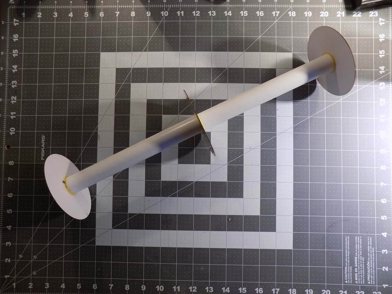
After epoxying on the motor retainer, I moved on to gluing the centering rings onto the motor tube, and to aid in this task, I used an unusual tool - the Estes Tube Cutting Guides.


These plastic rings are intended to help you cut a tube in two pieces, and to make a straight, clean cut. The guides come in a set of several sizes corresponding to standard Estes body tube diameters. Each one is made of two pieces. They come together and clamp firmly to a body tube, and you can then run around them with a hobby knife to make a clean cut with a factory edge.

I recently saw an experienced rocketeer online describe the Estes Tube Cutting Guides as "a waste of money." While I respect that rocketeer's level of experience, I'm afraid I have to disagree.

First of all, they're cheap. Depending on where you buy them, they cost between 8-12 dollars - hardly throwing your money away. Secondly, a tool is only a waste of money if you don't use it. And while it's certainly possible to get a clean cut of a body tube by hand, simply by wrapping a piece of paper around the tube and using that as a guide for your hobby knife, you do need a steady hand. If you need a little help, these cutting guides are great. But they even have other uses you might find handy.

In fact, I don't even use Estes Tube Cutting Guides for cutting tubes that often (I have other tools for that). But I do use them for other things. And often, I'll use them as a pushing tool to get centering rings on perfectly perpendicular to the motor tube.

For the sake of clarity, let's call one end of the motor tube the top, and one end the bottom. First, mark the tube where the centering rings are supposed to go, according to kit instructions (or your own design). We're going to start from top to bottom.

Slide the tube cutting guide onto the motor tube below the top centering ring mark. Don't clamp the guide down too tightly - it needs to slide on the tube.

Then place the centering ring on the tube, also below the top mark. Give some space between the centering ring and the mark on the tube. Then apply a bead of glue just below the top mark. Use the Tube Cutting Guide to push the centering ring up to your mark, thus creating a thick fillet of glue. With a fingertip, smooth the fillet and wipe away the excess glue (it will dry more quickly that way!).


After a few minutes, the glue will have grabbed hold of the centering ring, and you can remove the cutting guide before the glue dries completely. Even if it does dry, white and yellow glue don't adhere to plastic too well, and you should be able to remove the guide without too much effort.

Work from one end to the other, making sure you don't accidentally trap the guide between two centering rings!

As a result, you should end up with a motor mount with perfectly straight rings.


Of course, this doesn't work if you have a motor hook in the way, but for larger projects like this, it's a handy trick. It can even be used on some high power rockets - the BT-60 sized Estes Tube Cutting Guide fits a 38mm high power motor tube almost perfectly, since the outer diameters of the tubes are nearly identical.

Assembling the motor mount for a prototype of the AeroTech Monstra

I first tacked the centering rings on with wood glue, then made epoxy fillets

Perfectly aligned!

Adding Strength


Here's a step I'm not sure I needed to do, and in fact, might not have been a great idea, but I did it and there we are.

Since I may use more powerful motors than the two recommended by Estes, I thought it might be a good idea to add a bit of strength to the motor mount. There's a lot of distance between the motor tube and the edges of the centering rings, and it seemed to me that there was a lot of room for bending and failure because of that.

So I decided to cut some braces, or gussets, and install them for strength between the centering rings. I considered balsa, but I had some scrap corrugated cardboard lying around, and was able to quickly measure and cut it to the correct length.

I glued two in place, and that's when I started to wonder if this was perhaps not the best idea. I thought the gussets would be pretty light, but just installing the first two added some weight I could feel. Not much, maybe, but it really adds up in model rocketry. One thing I hadn't noticed until I got the first two gussets on was that the cardboard had a lot of packing tape on it, which added some mass.

But I started, so I decided to finish. It would have been stronger to have a set of three or four braces radiating out from the motor tube between each pair of centering rings. But that would have added a lot of weight, I worried. So I only did two, and I staggered them, in the hopes that they'd provide extra strength.


This might have been flawed thinking. I might have done better to have the braces go end to end. Or to make more of them, but keep them narrower, just bracing either the base of the centering rings, or the very edges.

Did I go to far? Should I have simply used the hook and engine block, flown the Saturn V on the recommended motors, and left well enough alone?

Well, it was too late at this point. The beefing up had already begun, so I'll just have to keep an eye on that center of gravity as I go, and try some fun motors. Worst case scenario, I'd end up building my second Saturn V sooner than I thought.

In the next post in this series, I'll install the motor mount.

Follow me on Twitter.

Like my Facebook page for blog updates and extra stuff.

Have a question you'd like to see addressed on this blog? Email me at iamtherocketn00b@gmail.com.