Showing posts with label AeroTech. Show all posts

Monday, March 18, 2019

Estes Saturn V Build - Getting Started - Tube Ends, Motor Mount


Click Here for Part 1

Maybe you recently purchased an Estes Saturn V, and yet you are afraid to begin building it. Am I ready for this? you might ask yourself. The Saturn V is listed as a Skill Level 4 kit (some might consider it more of a Skill Level 5 rocket). That term - Skill Level - can be intimidating for people. How do you know if you've graduated to the next one?

When I was first starting out, building Skill Level 1 rockets, I was nervous about building a Skill Level 2 kit, but it turns out a lot of these things are arbitrary. The Crossfire ISX, for example, one of two rockets which come with the Tandem X Launch Set, is considered a Skill Level 1 kit.


I actually think it should be labeled a 2, because some of the thick plastic parts require some cutting and trimming, and it might be a bit tricky for a new builder.

On the other hand, the Goblin is a Skill Level 2 kit, and for the life of me, I cannot figure out why.


The Goblin could hardly be a simpler build. The only thing I can think of is that it flies on D motors, and maybe Estes wants beginners to start out with something in the A-B-C range first.

Nevertheless, the Saturn V is an advanced rocket kit. It certainly shouldn't be one of your first builds. But, if you've been doing this for a while now, and if the rockets you're currently building look better than the ones you built when you started, you're probably better at this than you think. And, as I indicated in the title of my previous post, the thing about building a challenging kit like this, if it's a new level of building for you, is to take it one small step at a time. Follow the directions, work slowly, and think about what you're doing before you do it, and you'll probably end up with a pretty good looking Saturn V.

Can you screw this up? Sure! As I write this, I'm still in the early stages of building, and there's plenty of time for me to make mistakes. But there's no other equivalent rocket for you to "practice" on, and if you want a Saturn V, I suggest you take your time and build one. You'll definitely learn something, and I'm pretty sure you'll be happy with the results.

OK, on to the build! Here's a picture of the box with the contents inside. I should probably have taken pictures of all the parts laid out, but I didn't, so there we are. If you're building an Estes Saturn V, you can take a look in your own box and see all the parts.


Prepping the Tube Ends

The first thing I do is prep all the tube ends, by running a ring of thin CA - cyanoacrylate or hobby grade super glue - around the inside edge of both ends of each tube.


CA can be hazardous, so be careful. Specifically, it can glue parts of your body together (including fingers and eyelids, so keep it away from your face!), and large quantities of it can give you a bad chemical burn as it cures.

I try to do both ends of all tubes when building a model rocket. I used to only do the nose cone end, and sometimes I forget to do the motor tube, but I try to do all of them. Thin or medium thickness CA can be used. I like the thin stuff, because it wicks into all the paper fibers, even on thicker high power rocket tubes. Run a bit around the edge and quickly wipe off excess with a bit of paper towel or cotton swab.

The advantage of CA on the ends of the tubes are threefold. First, it hardens the paper fibers and adds a bit of strength to the ends of the tubes, which can be pretty thin on some rockets. Second, if you need to sand the inside of the tube to get something to fit, it will enable you to sand it nice and smooth, rather than shredding the paper. Thirdly, it protects the vulnerable edges of the tubes from water damage.

For example, let's say your rocket lands on some wet grass, and it takes you a few minutes to get to it. Well, if the rocket is painted, the body tube will be sealed from water damage, and be just fine. But if the ends of the tube - either the motor end or the nose cone end - aren't covered completely in paint, moisture can get in between the layers and quickly cause them to separate. Not a problem if you've prepped the ends with CA.

Or even way before that, when you're just starting to paint your rocket, say you're halfway through painting a nice coat of white when the spray can starts spitting chunks of pigment. You end up with sharp little bumps that look horrible, and would never allow you to put any decals on the rocket (this has happened to me many times). The solution is then to let the paint dry and wet sand the damaged paint off, using some wet/dry sandpaper and little bit of water. Again, the paint on the rocket will protect the tube from water damage, but if a dribble of water runs down the tube while you're sanding, and gets on the end of the tube, again, the layers will delaminate, and you'll have a terrible looking rocket. A bit of CA during building can help prevent this.

Assembling the Motor Mount

The motor mount for the Saturn V is similar to most Estes kits. There is a green thrust ring, sometimes called an engine block, which gets glued into the motor tube to prevent the motor sliding forward. There is a motor hook - a long one in this case, for longer E black powder and composite motors. And there is a sleeve to hold the hook in place on the outside of the motor tube. Rather than being a thin Mylar ring as is the case with low power Estes kits, this sleeve is a sturdy paper tube.


Instructions are standard. Run a ring of glue around the inside of the tube, insert the thrust ring and push it into place with the supplied spacer/pusher tube, cut a slit for the hook and insert it, then glue the sleeve into place over the hook.


Estes' instructions recommend two motors for this rocket: the Estes E12-4 black powder motor, and the Estes E30-4 composite motor, but in fact there are a number of motors which would fit. The hook gives you 95mm of space from front to back, so any 24mm composite motor from AeroTech would also fit (for shorter ones, you'd need to insert a spacer into the motor tube).

The AeroTech 24/60 casing, top, and 24/40 casing, bottom. The 24/60 is 95mm long - the same length as an Estes E12.

Distortion in the first photo makes the 24/60 casing look too long for the hook. It's not.

So, there are a variety of great motors, from Estes and AeroTech, available for you to try in the Saturn V. (Actually, the Estes composite motors were all manufactured by AeroTech, so if you've flown one of those, you've flown what is essentially an AeroTech motor).

But there are other 24mm motors which will not fit, and I happen to fly some of those. My club's on-site vendor is Animal Motor Works, and they deal mostly in Cesaroni composite motors. I have a casing for their three-grain motors, which is too long to fit with the hook and thrust block in place.

A Cesaroni 3-grain motor casing compared with an Estes E12 motor. CTI has 24mm motors as long as six grains!

One motor I'm looking to try in particular is the Cesaroni F30, which is a 3-grain composite motor which leaves a white smoke trail and burns for about 2.4 seconds - pretty long for a small composite motor. It's longer burn time is due in part to its core geometry, or the shape of the hole running down through the propellant grains. It's what's known as a moon burner, since the hole is off center.

The end of a Cesaroni F-30 motor grain, showing the core running down one side. The hole in the middle
is at an angle, and only about an inch deep, and is just there to guide the igniter into the side core.

A moon burner sounds pretty perfect for a moon rocket, so I decided to deviate from the instructions a bit.

Motor Retainer


Luckily, Estes makes a 24mm screw-on motor retainer. These come in two parts - one gets epoxied to the end of the motor tube, and the screw-on cap comes on and off to install or remove a motor. They use the 29mm version in their Pro Series kits, and the 24mm in a few of their smaller kits. They also sell both sizes separately, and they're great!

Nearly all composite motors on the market now have a built-in thrust ring on the back end. That's the wider bit you see on the back end of the AeroTech and Cesaroni casings above. They are also present on all AeroTech and Estes single-use composite motors. The nice thing about them is that they do the job of the little green engine block ring you normally glue into the motor tube. If you are lucky enough to get your hands on one of the discontinued Pro Series "builder" kits - like the Leviathan, Partizon, Ventris, or Argent - experienced rocketeers will tell you to leave the green thrust ring out of the motor tube. You'll only be limiting the size of motors you can use, because anything that's too long won't fit!

If I wanted to fly with a motor that didn't come with a built in thrust ring, I could simply create one, by wrapping a narrow strip of tape around the base of the motor until it was wide enough to prevent the motor moving forward. Then I could install it just like a composite motor, and screw the retainer in place.


Some people are skeptical that this would work - wouldn't the tape fail? And isn't that a violation of the Model Rocket Safety Code's rule about modifying motors?

But it really does work, and the MRSC has a rule against "tampering with" motors, which is not the same as putting a little tape on the outside of it. The NAR does not consider wrapping tape around a motor to be tampering. Heck, using a wrap of tape to get a friction fit in small competition models is common practice!

Mass Components and Stability


Whenever you alter the design of a kit, especially if you might be using a heavier motor than what was in mind when it was designed, you need to make sure the rocket remains stable. Your distribution of mass might change, and therefore the center of gravity (CG) may change. If the CG moves too far aftward, toward the bottom of the rocket, your CG may end up too close to the center of pressure (CP), resulting in a marginally stable rocket. Anything other than ideal flying conditions would make the rocket go unstable. Or worse, your CG may end up behind the center of pressure. In that case, you'd have an unstable rocket.

I'll need to keep my eye on stability as I choose motors. For now, though, I wanted to see if I was changing the CG by switching from a motor hook, sleeve, and engine block to a simple screw-on retainer.

You can see in the above photo, the kit combo weighs in at 8.7 grams, minus glue (which is negligible, if you use white or yellow wood glue).


The screw-on motor retainer weighs in at about 1 gram less than the kit parts, not counting the epoxy. Epoxy is a bit heavy, but I'd keep it to a minimum here. Also, while the kit retention system weighs more than the retainer, the retainer's mass is all concentrated at the very end of the motor tube, so the weight distribution won't be the same. But, at the very least, it didn't look like I'd be adding significant weight to the back end just yet.

The smooth inside of the motor retainer got sanded to roughen it up a bit, then glued on with a thin layer of JB Weld steel-reinforced epoxy. Any epoxy that goes where you don't want it (like inside the end of the tube or on the threads of the retainer - or on your cutting mat) can be cleaned up with rubbing alcohol while the epoxy is still liquid. Just use a cotton ball or swab and a bit of alcohol, and wipe off the excess.


After epoxying on the motor retainer, I moved on to gluing the centering rings onto the motor tube, and to aid in this task, I used an unusual tool - the Estes Tube Cutting Guides.


These plastic rings are intended to help you cut a tube in two pieces, and to make a straight, clean cut. The guides come in a set of several sizes corresponding to standard Estes body tube diameters. Each one is made of two pieces. They come together and clamp firmly to a body tube, and you can then run around them with a hobby knife to make a clean cut with a factory edge.

I recently saw an experienced rocketeer online describe the Estes Tube Cutting Guides as "a waste of money." While I respect that rocketeer's level of experience, I'm afraid I have to disagree.

First of all, they're cheap. Depending on where you buy them, they cost between 8-12 dollars - hardly throwing your money away. Secondly, a tool is only a waste of money if you don't use it. And while it's certainly possible to get a clean cut of a body tube by hand, simply by wrapping a piece of paper around the tube and using that as a guide for your hobby knife, you do need a steady hand. If you need a little help, these cutting guides are great. But they even have other uses you might find handy.

In fact, I don't even use Estes Tube Cutting Guides for cutting tubes that often (I have other tools for that). But I do use them for other things. And often, I'll use them as a pushing tool to get centering rings on perfectly perpendicular to the motor tube.

For the sake of clarity, let's call one end of the motor tube the top, and one end the bottom. First, mark the tube where the centering rings are supposed to go, according to kit instructions (or your own design). We're going to start from top to bottom.

Slide the tube cutting guide onto the motor tube below the top centering ring mark. Don't clamp the guide down too tightly - it needs to slide on the tube.

Then place the centering ring on the tube, also below the top mark. Give some space between the centering ring and the mark on the tube. Then apply a bead of glue just below the top mark. Use the Tube Cutting Guide to push the centering ring up to your mark, thus creating a thick fillet of glue. With a fingertip, smooth the fillet and wipe away the excess glue (it will dry more quickly that way!).


After a few minutes, the glue will have grabbed hold of the centering ring, and you can remove the cutting guide before the glue dries completely. Even if it does dry, white and yellow glue don't adhere to plastic too well, and you should be able to remove the guide without too much effort.

Work from one end to the other, making sure you don't accidentally trap the guide between two centering rings!

As a result, you should end up with a motor mount with perfectly straight rings.
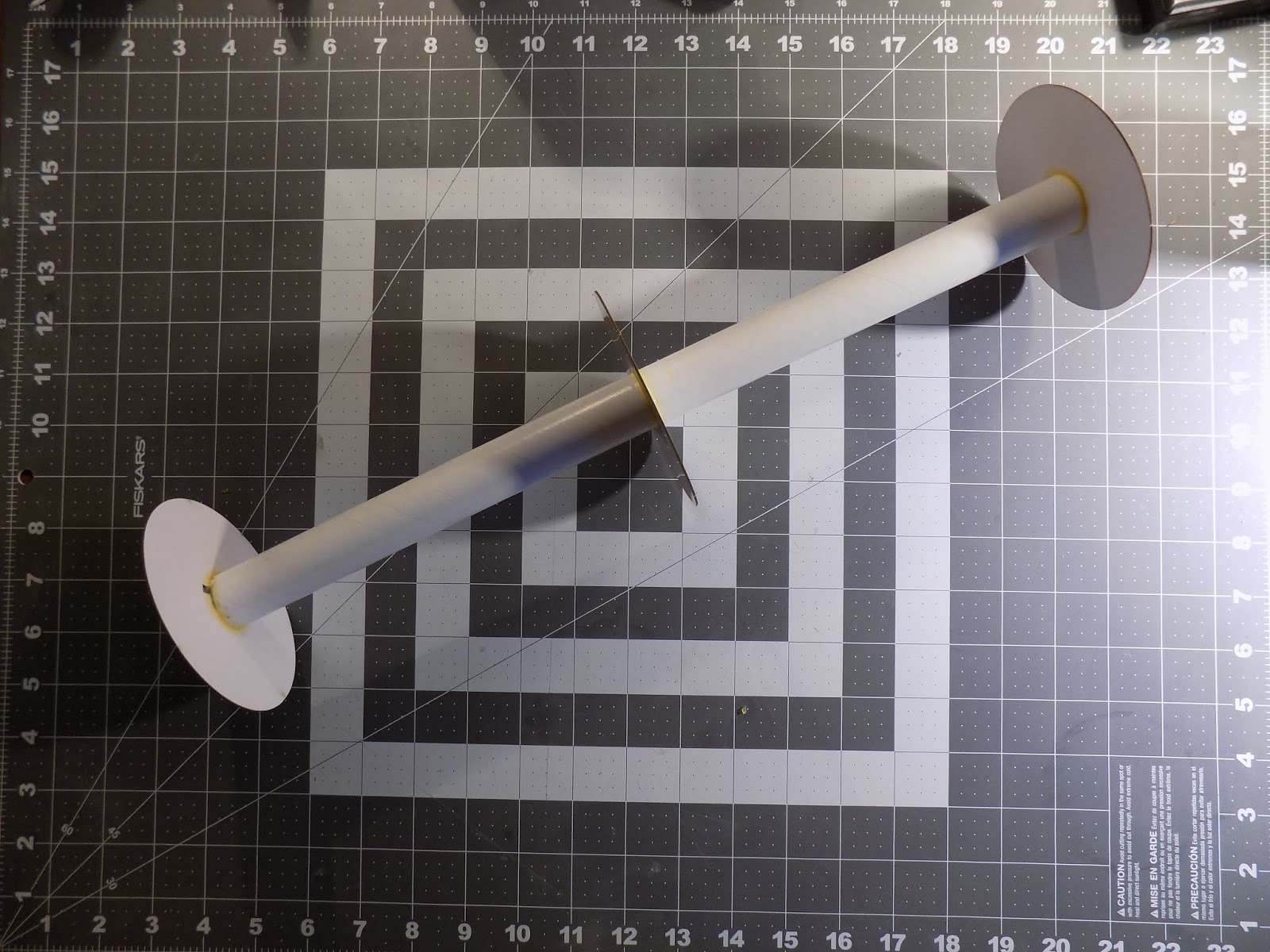

Of course, this doesn't work if you have a motor hook in the way, but for larger projects like this, it's a handy trick. It can even be used on some high power rockets - the BT-60 sized Estes Tube Cutting Guide fits a 38mm high power motor tube almost perfectly, since the outer diameters of the tubes are nearly identical.

Assembling the motor mount for a prototype of the AeroTech Monstra

I first tacked the centering rings on with wood glue, then made epoxy fillets

Perfectly aligned!

Adding Strength


Here's a step I'm not sure I needed to do, and in fact, might not have been a great idea, but I did it and there we are.

Since I may use more powerful motors than the two recommended by Estes, I thought it might be a good idea to add a bit of strength to the motor mount. There's a lot of distance between the motor tube and the edges of the centering rings, and it seemed to me that there was a lot of room for bending and failure because of that.

So I decided to cut some braces, or gussets, and install them for strength between the centering rings. I considered balsa, but I had some scrap corrugated cardboard lying around, and was able to quickly measure and cut it to the correct length.

I glued two in place, and that's when I started to wonder if this was perhaps not the best idea. I thought the gussets would be pretty light, but just installing the first two added some weight I could feel. Not much, maybe, but it really adds up in model rocketry. One thing I hadn't noticed until I got the first two gussets on was that the cardboard had a lot of packing tape on it, which added some mass.

But I started, so I decided to finish. It would have been stronger to have a set of three or four braces radiating out from the motor tube between each pair of centering rings. But that would have added a lot of weight, I worried. So I only did two, and I staggered them, in the hopes that they'd provide extra strength.


This might have been flawed thinking. I might have done better to have the braces go end to end. Or to make more of them, but keep them narrower, just bracing either the base of the centering rings, or the very edges.

Did I go to far? Should I have simply used the hook and engine block, flown the Saturn V on the recommended motors, and left well enough alone?

Well, it was too late at this point. The beefing up had already begun, so I'll just have to keep an eye on that center of gravity as I go, and try some fun motors. Worst case scenario, I'd end up building my second Saturn V sooner than I thought.

In the next post in this series, I'll install the motor mount.

Follow me on Twitter.

Like my Facebook page for blog updates and extra stuff.

Have a question you'd like to see addressed on this blog? Email me at iamtherocketn00b@gmail.com.

Monday, February 20, 2017

Current Projects #3 - Back on the Horse (Lots of Words and Lots of Pretty Pictures)


Admittedly, I've been sitting on this one for a while. Longer than I thought.

* * *

In December, I made a bad decision up in Maine. It was a windy day, the final launch of the season for me, and not good flying weather. The field up there is enormous, and perfectly flat. Nevertheless, it was cold and the wind was about umpteen miles per hour.

But we had rented a car, driven all the way up there, and I wouldn't get the chance to fly again until April. I had what the astronauts used to call Go Fever.

I had made a couple flights already with iffy results. The first was with my Quest Quadrunner, a four-motor cluster rocket.


The Quadrunner struggled off the pad and arced over without gaining much altitude. I thought it was due to the wind, which certainly was a factor, but when I got the rocket home, I discovered that one of the four motors failed to ignite.

Though it is charred from blowback, the motor at the bottom did not fire.

A seven-second delay was too long for this flight. The nose cone popped off and chute opened when the rocket was perhaps 8 feet in the air or less. There was some fin damage.


My next flight was on the scratch built Ceres B booster, from the book Make: Rockets: Down-to-Earth Rocket Science by Mike Westerfield.


It carries a camera payload and can fly on just about any 24mm diameter motor I choose - black powder or composite.

I intended to make two flights with the Ceres B. The rocket had previously only flown with an Estes E9-6 black powder motor, to an altitude of 764 feet.


I was planning to fly once on an E15 and once on an F12, both AeroTech composite motors, and take the rocket to a higher altitude.

The E15 flight went just fine until landing. Then the wind grabbed the parachute and dragged the rocket a good 75-100 feet through the sand. I had to run to chase it down.

Tracks left from the fins. I could tell where the rocket had
flipped over in the sand, as the tracks shifted positions.
Other than some cosmetic damage to the payload section (chipped balsa in the camera window), the rocket survived quite well, despite collecting some soil samples on the way.


I was ready to give up flying for the day after those two launches. But here's the issue: While the E15 is a single-use motor - just pop it into the rocket and fly - the F12 is a reload. You have to assemble it.

Left: AeroTech F12-5 reload kit - 3 motors per kit. Right: AeroTech Reloadable Motor Systems (RMS) casing.

Now, before I start rambling all about composite motors and reloads, etc. (I just deleted three whole paragraphs, due to that rambling), I'll just say this: you don't want to leave an assembled AeroTech reload just sitting around all winter and then try to use it months later. It has rubber O-rings and greased parts in it, and after a while, those parts can get compressed, and fail to spring back. When that happens, you can get hot gasses leaking where you don't want one, and the motor is likely to CATO - basically, the motor blows through the casing and can destroy the rocket.

On recovery, the Ceres B shock chord and chute got so tangled, and my hands were so cold, I couldn't possibly fly it again that day. It would require some major detangling at home.

But I had this motor. It was the first time I'd ever built an AeroTech reload. I couldn't just store it over the winter and use it in spring. And I wanted to know if I'd built it right (AeroTech reloads are generally more complicated to build than Cesaroni reloads. Cesaroni and AeroTech are the two most popular brands of reloadable composite motors).

The completed motor. The red cap on the lower left is the nozzle end. The red cap on the upper right is the ejection charge.
This is why I flew Ceres B on the E motor first. I wanted at least one good flight from in case my F motor had a CATO due to incorrect assembly.

So, I found myself in what seemed like a dilemma - on the one hand, I didn't want to fly any more, and risk losing or damaging one of my nice rockets. On the other, I had this unused AeroTech reload, and I needed to do something with it.

In retrospect, I suppose I could have taken the motor home, disassembled it, soaked the propellant in water to destroy it, and thrown it in the trash (that's how to properly dispose of a motor you don't plan on using - for example, if it's damaged and probably not safe to fly), and cleaned the grease off the casing. Call that motor a loss.

That's not what I did. Since this was my first time using an AT reload, it did not occur to me that this would have been a smarter thing to do.

Instead, I decided to fly the motor. One of the rockets I'd brought with me was one I was pretty proud of - my clone of the Estes Astron Sprint XL.


A very simple looking rocket, but I had gotten the paint about as perfect as can be expected. It was so shiny and smooth!

You may well ask why I would then risk flying this rocket in high winds. My reasoning is that, while I really love the way this rocket came out, it was basically built from scratch. I have the parts to make it over again, and in fact, it was only made as "practice" for the kit, which you can see unfinished at the top of this post, and which I started building over a year ago. I reasoned I could always build this one again, pretty cheaply, if, say, it got damaged by dragging through the dirt like Ceres B.

I installed the F12 motor into the Astron Sprint. There was some wiggle room between the aft end of the rocket and the motor hook, so to prevent the motor sliding back and forth during flight and ejection, I taped it in place. Not pretty, but I figured it should work.


Composite motors are more economical on a per-flight, total impulse basis. What I mean is that you get more power per flight per dollar than you would with black powder motors. A 3-pack of F12 reloads costs about $30, or about $10 per motor, which isn't bad at all, considering that these are F motors.

The casing, however, cost about $40. I didn't want to lose the casing, so I packed the chute using the Jolly Logic Chute Release, and set it to release the parachute at about 200 feet, if I remember correctly. This should have kept the rocket on the field, where I'd be able to recover it.

The Maine Missile Math and Science Club flies from a beautiful field in Berwick, Maine. It's a giant turf farm, with acres and acres of perfectly flat ground covered in short, soft grass. It's nearly like walking an a giant putting green - the grass is that soft. Flights to 10,000 feet are permitted there, and the landowner is happy to have us there. It's perfect for rocketry.

A mile and a quarter long by nearly a mile wide - a great launch site for New England

The Launch Control Officer counted down from five and pushed the ignition button - and the Astron Sprint XL took off like a shot! The F12 is a longer-burning, lower-thrust motor, but for a lightweight model rocket like the Aston Sprint XL, it's got plenty of kick. The rocket climbed a tower of thick black smoke, arced into the wind and nearly disappeared from sight.

At apogee, the nose cone popped off, and the rocket began to tumble. Despite having the parachute tightly held shut by the Chute Release, the wind took the rocket quickly down the field. At around 200 feet, the Chute Release opened, but the parachute was stuck shut - which, considering the wind, was a blessing.

However - and this is the heartbreaking part - despite the fact that the rocket stayed on the field, and the fact that I never lost sight of it completely, it landed in the one bad spot in the middle of all that beautiful turf. There is one long, narrow patch of swampy brush, and the Sprint landed somewhere in there.


I carefully kept a bead on it with my eyes, but when I got to the edge of the swamp, my heart sank a little. It can be easy to walk off course when following a missing rocket, but I knew I was on the right path when I found the one clue - a bit of blue Quest recovery wadding, which I nearly always include in my fireproofing. It must have fallen out of my Sprint as it passed over the edge of the swamp.


Hoping it had perhaps overshot the swamp, I ran around to the other side, but it was no use. I would have to trudge through shoulder-high reeds, thorns, scrub, etc, hoping to locate the downed rocket.

I walked into this, and it got pretty rough in there.


I nearly twisted an ankle a few times, got thorns in my leg, got my foot pinned in some underbrush... And the rocket could have been anywhere. I could have walked right past it several times.

After about 45 minutes in there, I realized I may never find it. I'd have spent more time looking, but it was getting late and dark, and very cold and windy, and the launch was winding down.

So, I lost the Aston Sprint XL clone. But worse - I lost the AeroTech casing and the Jolly Logic Chute Release - a loss of about $170 in one flight, not counting the rocket!

All this brings me to what I've been working on recently.

* * *

In September, Chris Michielssen wrote an inspirational blog post on the Model Rocket Building blog entitled Jake Parker - Finished Not Perfect. It spoke to me.

At the top of this post, you see the beginning stages of a build of the Estes Astron Sprint XL kit. I posted that on my Current Projects page - in December 2015! I only recently realized I had started this simple build that long ago!

The clone - the one I lost in December - was essentially "practice." I like to streamline my fins and sand them into airfoil shapes. It's something I don't find to difficult on a standard fin with four straight edges. But with an elliptical fin, I wasn't sure how to do it or where to begin. So I traced the kit fins onto some balsa, cut out some copies, and started practicing.

Here is a first attempt.


The leading edge is simply rounded.

The trailing edge is beveled, but the bevel doesn't go too far into the fin cord.

A cross-section, seen from the tip edge

Pretty basic, not perfect, but I was able to do it pretty quickly without too much difficulty. It seemed like sanding a better airfoil - and getting all the fins the same - should be feasible. So I tried doing a set of three, with a longer beveled trailing edge.


Marking a guide line down the root edge

The guide lines will help me keep my beveled edges even - so I hope.

A tip from the Model Rocket Building blog - medium CA - cyanoacrylate - on the fin edge, and
a bit of black marker will aid in keeping my sanding straight on the outer edges of the fins.

Guide marks for the beveled trailing edge


I've sanded a little closer to the center on one side of the fin than on the other.
The guide line shows me where I need to even things out.


Checking the evenness of the beveled trailing edges. They'll get sanded down further to nearly a sharp edge.

Once I had three fins which looked the same, I figured I had the technique down. And the fins looked so good, I decided I'd build a whole rocket around them. The current Estes BT-60 nose cone package you can buy includes the nose cone and tail cone from the Astron Sprint XL, so it would be simple to just make another one.

The nose cone pictured at the top is the Aston Sprint XL cone. The tail cone is attached.


I figured I'd end up with two of them, finishing around the same time.

Putting the shaped fins on the rocket. The tail cone was used to install the motor mount to the correct depth, and
was added later, once I had sanded off a slight overhang and filled in the seams from the molding process.


Once I got going, I spent a lot of time and care focusing on the clone. It paid off - the rocket looked beautiful. But the fact that I'd done so well on the clone made me hesitate on the kit - what if I messed up the fins? What if the paint job wasn't as nice? I'll work on it next week, I kept thinking.

This is what I've found. As I've gotten better at building and finishing, better at making my rockets look nice, I sometimes hesitate. I'm not so experienced that I can consistently get great results. I usually get pretty good results, sometimes really good, and sometimes horrible - especially with paint and sanding.

I finally decided I had enough half-built rockets lying around, and how hard could it be to airfoil those fins again, anyway? Besides, I could always make more.

Not only that, but while the Astron Sprint XL clone looked really pretty, it actually wasn't that great a flyer. It rolled really badly! (For rocket n00bs: roll is where the rocket spins around its vertical axis. Most model rockets do it a little. Some do it a lot. It's nice when you build one that doesn't roll at all - the goal for me with most rockets.)

Not only did it roll, but on its first flight, it rolled and wobbled. Such an odd flight! It meant that the center of gravity was not in line with its vertical axis. I wish I had video of that flight, because it was so unusual.

So, I did something when building the Sprint to make the rocket spin fast on every flight. It may have been unevenly sanded fins - one potential pitfall of trying to streamline them. I think a likely culprit was that I got both launch lugs on slightly crooked, causing uneven airflow and inducing roll.

The point is that the rocket looked pretty, but it was far from perfect - it was still just practice. There's nothing wrong with trying to improve your skills and make better and better rockets, but you actually have to build them and accept that you will make mistakes. That's always been a little tough for me.

The Astron Sprint XL needed to be finished, and I needed to start with those fins.


So, I did it, and it wasn't that hard, and they turned out looking great. I did these ones a little different than the last ones.

While on the clone fins, I beveled the trailing edge and merely rounded over the leading edge, on the kit fins I decided to do what I guess it's appropriate to call an elliptically rounded leading edge. That is, instead of simply rounding the edge, I beveled it to a narrower thickness first, then rounded that. This was in an attempt to give the fins a more "teardrop" cross section, appropriate for an airfoil. It's what I tend to do on my rockets with straight-edged fins, when I decide to airfoil them.

Guide marks at specific distances from the root edge

Crossing those guide marks with more marks a specific depth from the edges

Connecting the points where the guide marks cross. For most fins, I'd use a straightedge to mark a guide line.
For these, I was able to use the leading and trailing edges of the fins to connect the points.

Double-checking that the guide lines were the same distance from the leading edge.
I had done the same thing for the trailing edges, which you can see here are already sanded.

Once I got the trailing edges beveled, I gently rounded off any sharp corners left from sanding.
You can see the fin changes from flat to beveled in a nice, even curve.

I find guide lines important when airfoiling fins. Also important - checking my work against other fins.
In this case, I was lucky. I had an extra set from a kit which was smashed in shipping. The fins survived.

Once the leading edges were beveled to a narrower thickness, I rounded them over with a small piece of 220 grit sandpaper.

Leading edges

Trailing edges


Not exactly "teardrop-shaped," but close. A sharper trailing edge (left) and an elliptically-rounded leading edge (right).


Tip edge view
That's where I am at the moment with the Aston Sprint XL.

Speaking of fins, I'm also playing around with trying to shape fins on a scale model, by building them up and sanding them down. Here's a sneak peek.


This is just a first study. It's a work in progress, a rough draft of sorts. When I finish this little experiment, I'll talk about it on the blog.

Editing on the video series on building the Quest Superbird has gotten bogged down, so I've put that build on hold until I can sort out the video I have. But I've completed five videos so far. Click here to check them out if you haven't seen them.

A fun modification I've decided to try is this:


That's an Estes Crossfire ISX with a drag-reducing tail cone. I'm doing it more to have something that looks cool rather than to reduce drag, but that's the idea.

The tail cone is made from a leftover nose cone from an Apogee Components' Avion kit, from last summer's Rocket Camp. One advantage of building rockets with kids is that there are inevitably some left over parts.


Because this is a modification from the Crossfire's original design, it will require me to double check the stability before flight. I'll surely have something about this on the blog in the future.

Apart from that, I'm saving up to replace my AeroTech casing and Jolly Logic Chute Release. I hope to have more successes than failures to write about this year.

Follow me on Twitter.

Like my Facebook page for blog updates and extra stuff.

Have a question you'd like to see addressed on this blog? Email me at iamtherocketn00b@gmail.com.