Tuesday, April 5, 2016

Thousand Oaks "Model Rocket" Accident

A tragic story has been reported in the L.A. Times. Two teenagers were injured, one badly, at Thousand Oaks school, when a rocket exploded.

Bernard Moon. Image from the local ABC affiliate.

Update: One student, 18-year-old Bernard Moon, was critically injured, and has since died. News coverage has been heartbreaking, and the kids at this school are very shaken up by the incident.

* * *

However, the news report also refers to this as a "model rocket" accident.

I am terribly sorry that this accident has occurred, but I want to make something clear - this was not a "model rocket."

The two were "using a small propane cylinder to make a model rocket."

It's unclear whether they were trying to use propane as propellant, or whether they were trying to use a propane cylinder they thought was empty as the rocket body. Either way, this is in violation of the National Association of Rocketry Model Rocket Safety Code.
1. Materials - I will use only lightweight, non-metal parts for the nose, body, and fins of my rocket.

2. Motors - I will use only certified, commercially-made model rocket motors, and will not tamper with these motors or use them for any purposes except those recommended by the manufacturer.
What happened here appears to hearken back to the early days of home-made amateur rockets, before model rockets became available to the general public. This is October Sky stuff. And as much as we model rocketeers love the movie, and Rocket Boys, the book upon which it is based, this is dangerous stuff. Kids lost fingers, eyes, and sometimes lives doing this stuff. In the book, Sonny's mother tells him over and over, "Don't blow yourself up."

She had reason to worry.

That is part of why I write this blog. I'm trying, in my small way, to make people aware of model rocketry as a hobby, how to do it, and how to do it safely. This is a niche hobby - a strong, growing hobby - but one which is practically unknown outside those who practice it.

In the 1960s, 70s, and 80s, model rocketry had a much higher public profile. Today, people have kind of forgotten it exists. Outreach from model rocketeers to spread the fun, the educational benefits - and the safe practices - of model rocketry to a wider audience is important. It's important to grow the hobby, so it can be here for us to enjoy for a long time.

But it's also important for another reason. Sometimes, someone unacquainted with the NAR or model rocketry in general gets the idea, I'd like to build a rocket! And they may turn to the Internet for information.

And there's some not-so-great information out there. There is some dangerous information, often put out there by people who have simply been lucky enough not to blow themselves up yet.

Spreading the hobby means that those who develop an interest in "building a rocket" are more likely to know that there are reliable, legal, safe resources out there for them to work with.

And if model rocketry has a higher public awareness, the news media, who can't be expected to keep up to date on every obscure hobby out there, would be less likely to report incidents like this as a "model rocket" accident.

And that is important because we don't want people unfamiliar with the hobby - citizens, law enforcement, legislators - to think that this is a crazy hobby practiced by crazy people, and that it should be outlawed.

In my job and in life, I often come in contact with people of influence. Not as much here in Boston as I did back in Bloomington, Indiana. But I still do sometimes. And whenever I get a chance, I chat a little about my interest in model rocketry. Maybe that person will develop an interest. Maybe they have kids, and that will get them interested. Maybe they'd just like to check this thing out.

I've talked with - and shown my blog and some of my YouTube videos to -  police officers, firefighters, teachers, business owners and even a Deputy Mayor. You'd be surprised who finds the conversation interesting, and who wants to know more.

Keep building and flying - safely. And share this hobby with others.

Update #2: A new report states that authorities are making it clear that this was not a store-bought hobby rocket.

Like my Facebook page for blog updates and extra stuff.

Follow me on Twitter.

Monday, April 4, 2016

Playing With the Flight Simulation

Now that we've run a first simulation using Estes C6-5 motors, let's try a couple things. What if I'd built the rocket without streamlining the fins? What might the altitude difference be?
I'll go back to the rocket design and set all the fin cross sections to "square," then run another simulation. With six streamlined fins, the simulation predicts an altitude of 936 feet. What about with six square fins?


According to OpenRocket, the increased drag from square fins over streamlined fins has cost us altitude - we've gone from 936 feet down to 692 feet - a significant difference!

Is this accurate? It's hard to say. Some people claim that rocket simulators overestimate altitude predictions somewhat, or that they overestimate the value of airfoil-shaped fins. I can't make a claim about it without testing it myself. But there will surely be at least some difference in altitude.

OK, let's go back to the simulation which matches the rocket we're using here. With streamlined fins, I should be able to expect an altitude of somewhere over 900 feet on two C6-5 motors. What if I'm flying on a smaller field with trees on the edge, or it's kind of windy? What if I want to fly the rocket, but not go so high?

Simply create another configuration in the Motors & configuration tab. Let's try the three most common 18mm motors - the A8, the B6 and the C6, and compare them.


I can highlight all three simulations and run them at once.


Looks like I can keep the rocket to around 400 feet on the B motors for a small field or windy day, and even lower with the A motors - 140 feet - for an even smaller field, or maybe a simple demonstration of the rocket. Liftoff velocity appears safe enough for all three configurations, and I accurately guessed which delay times I'd need to select for each motor combination.

Let's try one more thing. Let's compare the Estes C6-5 motor, which we've been using for all the simulations up to this point, with the Quest Aerospace C6-5 motor.

As you may have read, the C in this motor designation refers to the total impulse of the motor, between 5.01 Newton-seconds and 10 Newton-seconds. The 6 refers to average thrust, measured in Newtons. So, a C6 motor is supposed to have an average thrust of 6 Newtons, and a total impulse of up to 10 Newton-seconds. Click here for a refresher on motor basics.

However, despite what you may have read, an Estes C6 motor does not have an average thrust of 6 Newtons. Its average thrust is about 4.7 Newtons. The average thrust of the Quest motor is even lower - 3.5 Newtons. Both motors have a total impulse of 8.8 Newton-seconds.

This leads to something very interesting. Since total impulse is approximately equal to average thrust multiplied by burn time of the motor, the lower-thrust Quest motor should burn for a longer time period. And, in fact, it does. The Estes motor burns for 1.9-2ish seconds, while the Quest motor burns for 2.5 seconds - 25% longer! Both motors impart the same amount of force to the rocket - 8.8 Newtons. The higher-thrust Estes motors make the rocket fly faster.

And here's the really interesting part. There are two forces keeping a rocket from flying upwards forever: Gravity and drag. Gravity is a constant. Drag is influenced by a number of things, but especially by the velocity of the rocket. Drag increases as a square of velocity. So, if you double a rocket's velocity, drag increases four times. If you triple the rocket's velocity, drag increases nine times!

With the right combination of optimal mass, lower thrust, and longer burn time, often the lower-thrust motor will take a rocket to a higher altitude than it's higher-thrust counterpart of the same total impulse.

Let's test this out in the simulation.
On the Motors & configuration tab, I'll create two configurations, one for the Quest motors, and one for the Estes. To avoid confusion, I'll click on the Rename configuration button and type in the correct brand name of the motors I'm using for each configuration.


Going back to the Flight simulations page, I run both simulations at the same time. Here are the results:


As you can see, the Quest motors take the rocket higher, breaking 1,000 feet in altitude. Optimum delay for both flights is just over 5.5 seconds, so C6-5 motors will work well regardless of which brand we select.

Let's unpack the information here.

On the Quest motors, the rocket leaves the launch rod traveling at 48.9 mph, 17.7 mph faster than on the Estes motors, with which it leaves the rod at 31.2 mph. At this point, the rocket with Quest motors is experiencing much more drag than the rocket with Estes motors. But the story isn't over - the motors are still burning, and the flight has just begun.

We've already established that the Estes motors have a higher average thrust than the Quest motors, so why is the rocket with the Quest motors traveling so much faster?

The answer lies in the thrust curves* of the individual motors.

Here is the thrust curve for the Estes C6 motor:


As you can see, in under a quarter of a second, the thrust peaks at nearly 12 Newtons, then settles back to a lower-level thrust of under 5 Newtons for the rest of the burn. This initial, peak thrust is pretty common in black powder model rocket motors - a peak early in the burn, followed by a lower thrust for the rest of the burn - and has to do with the surface area of the propellant being burned at a given moment.

For comparison, here's the thrust curve for the Quest motors:


Here, we can see a dramatic difference. The initial thrust peaks at over 22.5 Newtons - much higher initial thrust than that of the Estes motors. After the peak, the thrust reduces to a much lower level, but for a much longer burn time.

We've seen that the rocket with Quest motors leaves the rod at much higher velocity, which means higher drag, and but that the average thrust is much lower. Why does the Quest rocket go higher?

Let's look at the flight simulation plot for both flights from OpenRocket.

The Estes flight plot:


And the Quest flight plot:


We can see the vertical velocity - the blue line - increase until motor burnout occurs, at about 2 seconds for the Estes motor, and for about 2.5 seconds for the Quest motor. By the time motor burnout occurs, the Estes rocket has caught up with and surpassed the velocity of the Quest rocket, by about 9 miles per hour.

But look at where burnout occurs for each rocket - at around 310-325 feet for the Estes rocket, and around 400 feet for the Quest rocket. Once motor burnout occurs, the rocket will only slow down - and the Quest rocket has a head start of about 75 feet when coasting begins!

The Estes rocket is traveling faster, but can't catch up to the Quest rocket. Aerodynamic drag increases as a square of the velocity, so already the Estes rocket is experiencing more drag due to its increased velocity.

And the air gets thinner as altitude increases, so drag decreases as you go upward. How much difference in atmospheric density will the rocket experience in 75 feet? Well, not much, but there is an difference.

So the Quest rocket, while traveling 9 mph more slowly than the Estes rocket at motor burnout has a 75 foot head start at coasting, and experiences less drag due to being higher in the air and traveling more slowly.

Playing around with simulations like this is a good way to see how your rocket can reach higher altitudes. But maybe a difference of 80 feet in altitude isn't such a big deal to you. Well, there's another reason to try Quest motors. Longer burn launches are fun to watch! 2.5 seconds may not seem like a long time, but when it comes to model rocket motor burns, you really do notice a difference.

*Accurate thrust curves are hard to find. There were several thrust curves on Thrustcurve.org for these two motors, and not all of them agreed with one another completely. I selected the two thrust curves to best illustrate the point here.

A Word About Payloads

The Quest Magnum Sport Loader is a payload-carrying rocket. It's specifically designed to loft 1-2 raw eggs. Earlier in this series, I modified the payload bay so I could fly the rocket with a barometric altimeter.

Static ports - tiny air holes drilled into the payload compartment - allow the air pressure inside
the rocket to match the air pressure outside so the altimeter can get an accurate reading.
If you do add a payload to your rocket, whether it's an egg, an altimeter, a camera, or a little toy astronaut, you will add mass. To get an accurate simulation, you'll want to repeat the steps with the payload installed.

The Jolly Logic Altimeter 2 adds 9.9 grams.

This 808 keychain camera - a common
payload - adds 14.4 grams.

This foam rubber padding, which I'll use to hold and protect
the altimeter, adds 2.1 grams.


The rocket with the altimeter and padding now weighs
118.4 grams. I'll need to adjust my sim for greater accuracy.

Eggs in particular are pretty heavy. Even if you're not terribly concerned about the accuracy of the altitude prediction, if you add a heavy payload, you want to run a new simulation with the new mass of the rocket, for safety. I know I can fly the Magnum Sport Loader with one egg on two C6-5 motors. But with two eggs, I might need to select a shorter delay time.

* * *

There's one more feature in OpenRocket I'll show you quickly - the different ways you can view the rocket design.

In the top left-hand corner of the bottom panel, where you see the rocket, you can select View Type.


We've mostly seen the rocket in Side view, which shows you the basic design in a 2-dimensional layout. You can also see the rocket from the back, by selecting Back view.

This feature can help you accurately place launch lugs, odd fins, cluster motor tubes and other items on the rocket, by sighting straight up from the aft end.

There are also three different 3-dimensional ways to view the rocket. 3D Figure and 3D Unfinished both show the rocket as a see-through but 3-dimensional image. The main difference is that in 3D Figure, all the components are color-coded. I suppose this is to help you distinguish individual parts more easily when looking at the rocket.


Finally, 3D finished will show you the completed rocket. The components default to natural colors (tan body tube and balsa fins, white plastic nose cones), but you can change the color to get a final idea of what the paint job might look like.


The 3D views all allow you to rotate the rocket, both vertically an horizontally, so you can get a good look at the whole thing. If you're designing your own rocket, it's good to be able to turn the thing around and look at it from all sides to decide whether you like the looks of it before you start building.


* * *

How accurate are these simulations? Will my rocket actually fly to an altitude close to the 945-odd feet predicted? And if the prediction is inaccurate, how can I improve it?

I don't yet know the answers to those questions, because I haven't tested it out yet. And despite the fact that it's a free, excellent tool for modern rocketeers, there are a few things OpenRocket doesn't take into account: additional drag caused by the static port holes, or the shoddy work I did on my airfoils, for example.

I'll return to this subject when I've had the chance to launch the rocket with an altimeter on board. We'll see how accurate the predicted altitude is, and we'll try to figure out what went wrong if the prediction is totally off. The next launch is scheduled for April 23.

Stay tuned.

Like my Facebook page for blog updates and extra stuff.

Tuesday, March 29, 2016

Estes Goblin - Finished!


The Goblin is a classic Estes kit. I believe they used to send it as a free gift when people ordered a certain amount of stuff. The Goblin had been out of production for years, and was brought back as a clone by Semroc.

Due probably to the popularity of the Goblin, Estes re-released their kit, so now you have a choice. Both rockets look pretty much the same, and are the same size. The main difference is the nose cone - the Semroc version uses balsa wood, while the current Estes kit features a plastic nose.

The Goblin flies on 24mm D motors. It's a very simple rocket, but this build gave me a lot of trouble! I made so many mistakes, starting with gluing the fins on. I accidentally tore the very first fin off while the glue was nearly, but not quite, dry. I had to cut it off and sand the root of the fin, but there was some tearing of the body tube.


Well, I didn't want to accept this flaw, and needed a way of covering it up. So I elected to do the fin fillets with epoxy, filled with microballoons - microscopic spheres of glass.


 This makes epoxy thicker and easier to sand if you need to. It also allowed me to get some nicely smooth, curved fillets.

Epoxy fillets make the rocket heavier, and it's probably overkill for most small rockets. But it makes a larger footprint, which successfully covered the torn paper airframe.


When sanding the primer, I sanded through and actually cut into the paper body tube, raising fibers. This would have created some hairy spots on the final paint job. So I soaked the spots with thin CA - cyanoacrylate or Super Glue - and sanded the fibers off. After re-priming, the surface looked fine.

Then I had issues with the paint! I often use Rust-Oleum 2X enamel paint, which I did here. It's a pretty good paint, but some cans of it turn out not so great. I got a really rough texture, with part of the rocket looking like sandpaper, and part of it looking like dried out earth - dark cracks all over the fins. I didn't take a picture of that, unfortunately.

I used wet/dry sandpaper to sand the rough paint off. This took a long time.

I got a new can of Rust-Oleum Marigold paint - one of my favorite shades of yellow from Rusto.

The new paint went on fine, and apart from a little flaw around the edges of the black on one fin, I'm satisfied with it.

Despite all the trouble it gave me, the Goblin turned out quite nice. I did have to leave off one waterslide decal - the Estes logo, which is supposed to go just below the black band around the rocket. Unfortunately, I cut part of the decal off when I was trimming it from the decal sheet.

Oh, well...


Like my Facebook page for blog updates and extra stuff.

Follow me on Twitter.

Monday, March 28, 2016

Repairing and Enhancing the Quest Magnum Sport Loader - Part 5: Finishing the Sim

Click here for Part 1 of the series

Click here to start with Part A of the rocket simulation part of the series

A Few More Details

We found the true weight and Center of Gravity (CG) of our rocket in the last part, and input that information into our simulation. I just have a few more details to change, then we can run a simulation.

The fins that came with your rocket were most likely balsa, and were cut from a flat sheet. As a result, the edges of the fins will be squared, as you may have noticed.


However, it is possible to shape these fins by hand so that they have a more streamlined profile. The main purpose of doing this is to reduce aerodynamic drag (or wind resistance) so that the rocket can reach a higher altitude. There are a few ways to shape fins to reduce drag, but the main two you will see rocketeers use are either to simply round the forward and leading edges, or to sand the whole fin into a symmetrical airfoil shape.

The fins from the Quest Big Dog. The four fins on the bottom are from the kit, and are square. The fin on top is one I
cut from a sheet of balsa in order to practice sanding the fins to an airfoil shape before trying it on the kit's fins.
Streamlining your fins will affect the rocket's altitude. How much is somewhat unclear. The Handbook of Model Rocketry states that you may double your altitude with airfoiled fins. I find that rather unlikely. But sometimes you will encounter some people on various online rocketry forums who claim that it makes no difference, or "no significant" difference. That leads to the question "what does a 'significant' increase in altitude mean?" More than 10 feet? More than 10 percent? More than 25 percent?

Some classic Estes publications put the question to scientific testing. I have a feeling that a good airfoil with a good, smooth finish, may help you increase your altitude by a significant, but not miraculous, amount. How much of an increase, I'm not prepared to say without testing it out myself, so I have assigned myself the project of doing comparison testing and publishing the results on this blog. In my 40's, I have found the perfect 7th grade science project. If only I had started building rockets earlier!

Anyway, a well-streamlined fin certainly makes at least some difference in altitude, and OpenRocket takes that into account. When you first create a simulation, the default fin cross section is square. If you leave the fins on your rockets square, then you're basically done.

The Quest Magnum Sport Loader has two sets of fins. On the forward set, I sanded an airfoil shape, and on the aft set, I simply rounded the leading and trailing edges.

The forward fin set - airfoiled

The aft fin set - rounded
Now these fins - especially those airfoils - are not my best work. They were an early attempt. A couple of them are a little lopsided. But, OK, it's technically an airfoil shape, so I'm going to put that information into my simulation.

Click on a fin set, select Edit, and change your fin cross section to whichever it is on the rocket.


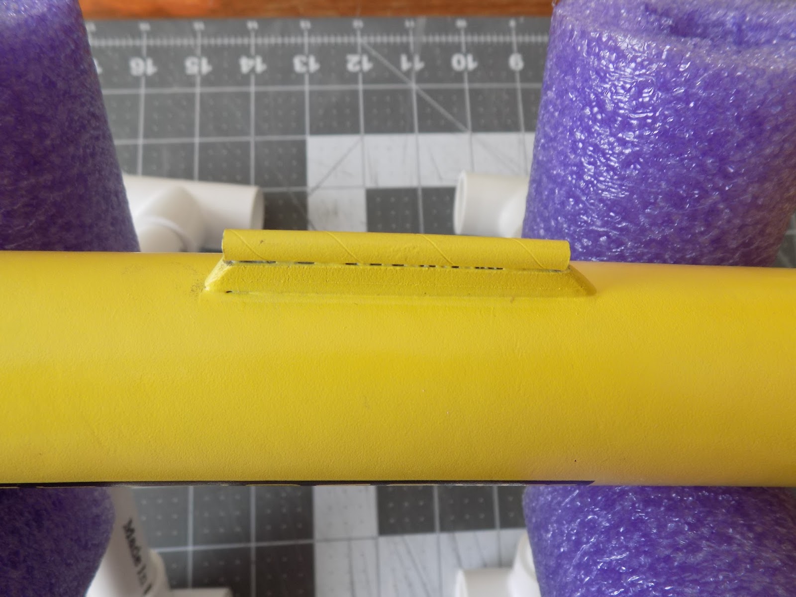
This rocket also has a launch lug standoff so that the launch rod will not hit the payload section. I've rounded that too, so I'm going to select that component (which, in OpenRocket, is simulated by creating a single fin) and change the cross section to Rounded.

Again, not my best work, but whatever.
Finally, I'll change the finish on the rocket. Do you have a really slick, polished surface, or is the paint job a little rough? You can change that in your simulation. Click on each component and select Component finish, then use the drop down box to select the finish which best approximates your paint job.


There's one other thing I want to do, just for curiosity's sake. I'm about to run a simulation with motors installed. I have the CG in the right spot on the simulation. When I "install" motors, it will shift the CG aftward. I want to see how accurately it will do that.

I install two real Estes C6-5 motors into the real rocket, then find the new CG, as I did in the last post. Then I'll mark that spot with tape and measure it.


With two C6-5 motors installed, it looks as though the CG is now at 36.7cm from the tip of the nose cone. The original CG was at 29cm. So the CG has moved aftward by 7.7cm. We'll come back to this in a bit.

Running a Simulation

We've done all the tedious detail work of making sure our simulated rocket matches the real thing, as closely as we can. Now comes the fun part - finding out how high we can expect different motors to take the rocket.

We're looking for three important pieces of information from a simulation. 1) How high the rocket should go, 2) how fast the rocket will be traveling when it leaves the launch rod, and 3) what the ideal delay time is.
Near the top left of the screen, you'll see three tabs. We've been working in the design tab so far. To get started with a simulation, we need to add a motor or motors. Click on the Motors & Configuration tab.


You will see the following screen.


Here you see three columns. One is called Configuration, and the others are Yellow Motor Tube 1 and Yellow Motor Tube 2. Because I have a cluster rocket, I have two motor tubes, and I have to select a motor for each tube. It would be the same if I had a two-stage rocket - I would need to select a motor for each stage. If you have just a single-motor rocket, you will only have one motor tube. It might be called "Motor tube" or "Inner tube" or even "Body tube," whatever the person who made the simulation decided to call it. But it's to the right of the column called "Configuration."

Above this is a button labeled New Configuration. Click on it.


Now you have a table. The column on the left is the configuration name and the column or columns on the right tell you what specific motor is in each tube.

Below the grid are a few buttons, two of which are labeled Select motor and Remove motor.

Click on Select motor.


A box pops up with a huge list of commercially available rocket motors, from tiny little 1/2 A motors to monster-sized, Level 3 high power O motors with as much total impulse as a Sidewinder missile!

For now, let's see what those Estes C6 motors will do. I'll scroll down until I find the Estes C6 motor, then select a delay. I'll try 5 seconds, since I've got a ton of those C6-5 motors.

Click on the motor you want, then use the drop box to select a delay time from the ones available, then click OK. Because I have two motor tubes, I have to do this twice.

Then, this happens:


The Configuration name is now 2xC6-5. Each motor tube has a motor installed. The CG has shifted aftward. And down in the left-hand corner, we now see an altitude prediction - 945 feet (your units may be in meters or feet. You can change your preferences as you like) - as well as maximum acceleration (169 meters per second squared - or 17.3 Gs!) and maximum velocity (87.6 meters per second, or about 198 miles her hour!).

Let's get back to the real rocket for a moment. With real motors in the real rocket, the real CG has shifted aftward to about 36.7cm from the tip of the nose. In our simulation, the CG is calculated to be at 35.9cm from the nose. Pretty close - it's a difference of only 8mm. Still, with over half a centimeter difference between simulation and reality, it's a good argument for always checking your stability when you build your own design or alter a kit.

Next to the Motors & Configuration tab is the Flight Simulations tab. Click on it.


A page appears, and on it are five buttons and a table with the configuration you just entered on the Motors & Configuration tab. None of the information is filled in the table yet.

You can highlight Simulation 1 and simply press Run simulations, but let's try Edit simulation first.


A box pops up with lots of information - variables you can play with. For now, though, let's just worry about the Launch rod length.

Let's assume you're using an Estes launch pad, which a lot of beginners start with. The launch rod is 33 inches in length. Maybe your launch lug is not at the base of the rocket, though. Maybe, like on my rocket, it's a few inches forward of the aft. And maybe you want to use a standoff to lift the rocket up an inch or two off the blast deflector so you have room to hook up igniters.

I'm going to click on "mm" and change the units to inches (because I know what 33 inches is without having to look it up), and change it to 25 inches. That's pretty short, but we'll see if it's OK.

Once you've edited the simulation to your liking, hit Close. Then, with Simulation 1 highlighted, press Run simulations.

The table will fill in with flight information.


The green dot means that we have a current simulation. If I change anything in the rocket design, the dot will turn red, and we will have to re-run the simulation for OpenRocket to verify that it is an up-to-date, valid simulation.

The red check mark is a warning. There's some issue of concern. If you hover over the check mark, you can see what the problem is.

In this case, I know it's no big deal. Discontinuity in rocket body diameter is a warning you get when you have components, such as a body tube and a transition, which do not match. There are times when you have a real mismatch, but in general, if the rocket is built correctly, you don't have to worry about it.

Warnings to look out for are things such as Velocity too low off launch rod or Recovery device deployed at high speed.

Let's look at the other information here.

Velocity off rod: 29.7mph

A rocket needs to be traveling fast enough for the fins to do their job of keeping the rocket stable. In this simulation, our rocket has gone from 0 to 29.7 miles per hour in a mere 25 inches!

Is this fast enough, though?

You may encounter several figures about rocket velocity off a launch pad. Some sources say "at least 30 miles per hour" (such as Mike Westerfield's book Make: Rockets: Down-to-Earth Rocket Science). Thrustcurve.org recommends at least 15 meters per second or 50 feet per second. This is a bit faster than 30 miles per hour. I've even heard that recommended minimum liftoff velocity can be as low as 20 mph, but only on a nearly windless day.

A good base rule of thumb is that the rocket should be traveling at least five times the speed of the wind. So, on a day with light, 5 mph winds, 25mph might be fast enough. Faster is often better, though some rockets are specifically designed to lift off slowly, so you can see them better. Low and slow is a term you might hear - the rocket doesn't zip out of sight, and doesn't go too high.

However, there is such a thing as too slow, and anything below 20mph should probably be avoided entirely. Slow lifters are fine on calm days, but shouldn't be flown on windy days.

Still, faster is better. If your liftoff speed is too slow, you have a couple options: Pick a higher thrust motor, or a longer launch rod. I don't actually use Estes launch rods. I buy steel rods from the hardware store, which are at least 36 inches long.

Let's see what happens if we add just three inches to the launch rod. I'll go back and edit the simulation, then run it again.


Now the rocket is leaving the pad at over 30 mph. Sometimes, just using a slightly longer launch rod is the answer.

Apogee: 936 feet

Pretty self-explanatory. It differs slightly from the 945 foot apogee prediction in the design window. I'm not sure why this is, but it may have to do with the 5-second delay used. And sometimes, when you close an OpenRocket file, then re-open it later, the apogee prediction is slightly different. Again, I'm not sure why. But it's always in the ballpark.

Velocity at deployment: 16.2mph

This is the speed of the rocket when the recovery system - parachute, in this case - deploys. The object is to deploy the recovery system as close to apogee - and as close to 0mph/mps as possible. Here, the rocket is moving about 16 miles per hour. Which leads us to the next piece of information in our simulation.

Optimum delay: 5.67 s

Estes C6 motors come with three different delay times* - 3 seconds, 5 seconds or 7 seconds. The C6-5 motors we selected have a 5-second delay. The optimum delay would be 5.67 seconds. What we have to do is to select the delay that gets us closer to that number.

Because the optimum delay is slightly longer than the actual delay of the motors we are using, the rocket is still traveling upwards when the ejection charges fire. But it's pretty close to apogee, and the rocket is flying acceptably slowly at that point.

Sometimes you will have an optimum delay which falls somewhere between two available delay times for a particular motor. In that case, you need to make a decision. I usually select the delay which is closest to the optimum.

Of course, you may select a different delay. If I were to use C6-7 motors, for example, the rocket would have the chance to coast all the way to its highest possible apogee, where it would arc over and begin to descend, and a moment later, the recovery system would deploy.

Here, I've run simulations on three different configurations at once - trying all three delays available with the Estes C6 motors.


Note the Velocity at deployment speeds, as well as the apogees. With a C6-3 motor, the flight gets stopped short by the ejection charge, only reaching 838 feet, and the warning tells us that the recovery system deployed at high velocity - nearly 64 miles per hour! That could rip the rocket apart when the parachute attempts to deploy.

The rocket does go slightly higher with the longer delay. The deployment velocity is a little faster, as the rocket is now falling, but I don't get a warning about high speed deployment - just the rocket body diameter warning as before. This motor would probably be OK. But I'd play it on the safe side in this case, and stick with the C6-5 motors.

Max velocity and Max acceleration, we've already noted above, so let's skip to...

Time to apogee: 7.27 s

From launch to apogee in this simulation takes just over 7 seconds. If you break down what we know about this motor, it makes sense.

According to Thrustcurve.org, this motor burns from about 1.9-2 seconds. The actual burn time will vary slightly from motor to motor. The delay grain is 5 seconds long. Again, there will be some slight variation in motor quality and performance. So, a motor that burns for about 2 seconds, with a delay grain of about 5 seconds, plus a split second delay from the ejection charge firing to the rocket body tube pressurizing and the nose cone popping off give us a little over 7 seconds of upward flight.

This number - 7.27 s - is more precise than what it would be in reality. The variation of motor performance will change this time ever so slightly, and in fact, if you run the simulation again, you'll probably get a different number. I'm not sure why that is, but it is.

Flight time: 65.2 s

This is the time from motor ignition to touchdown. Our flight lasts over a minute long.

Ground hit velocity: 11.1 mph

This is the speed at which the rocket lands under parachute, and it's about 16.28 feet per second.

That's actually pretty slow, and will provide us with a nice, soft landing. But it also means the rocket may drift far from the launch pad on a breezy day. I'm using a 15 inch parachute in this simulation. I might try running a simulation with a 12-inch parachute, and seeing if that's still safe.

Plotting the Simulation Data

 We can also plot the simulation on a graph. The right-hand button on the Simulations tab says "Plot / export." Click on it. The following dialog box pops up:


You can plot lots of information from the simulation on a graph. The X axis defaults to represent time, in seconds. The three default pieces of information on the Y axis are altitude, vertical velocity, and vertical acceleration. You can add or remove information to plot, either by clicking on the New Y axis plot type button to add information, or by clicking the red X button next to a Y axis type to remove information. You can also change units - say, by plotting the altitude in feet or meters, or electing to see vertical acceleration in meters per second squared, feet per second squared, or G forces, for example.

To make things simpler and cleaner for this post, I'll remove vertical acceleration, and simply plot the altitude and vertical velocity over time.

Once you have decided what data to plot, simply click the Plot button in the lower right of the dialog box.

A small graph will pop up. You can enlarge it by clicking on one edge and dragging it.


Here, we see a number of events, starting with motor ignition, at T-0.

The blue line, representing vertical velocity, shoots upward, as the rocket accelerates through the burn of the motor. The red line represents altitude. Then, at just around 2 - 2.1 seconds, we see a line representing motor burnout. The rocket enters the coasting phase of flight at this point. The altitude continues to increase,  while the vertical velocity starts to go down, as gravity and aerodynamic drag slow the rocket down.

Between about 7 and 7.5 seconds, we see the recovery device deployment and apogee - the highest point in the rocket's flight. With the parachute deployed, the red altitude line descends slowly to 0 feet above ground level, at just after 65 seconds.

Cool, huh?

Now that we've covered the basics of running a flight simulation, we'll break here. In the next post in this series, we'll try different motors, talk briefly about flying payloads, and tinker with a couple other things.

Click here for the final installment

Like my Facebook page for blog updates and extra stuff.

Follow me on Twitter.